If the two input has exact the same phase (frequency) the phase detector will not activate the current pump,
so no current will flow (3-state).
If the phase difference is positive (f1 is higher frequency than f2) the phase detector will activate the current pump
and it will deliver current (positive current) to the loop filter.
If the phase difference is negative (f1 is lower frequency than f2) the phase detector will activate the current pump
and it will sink current (negativ current) to the loop filter.
As you understand, the voltage over the loop filter will vary depentent of the current to it.
Okay, lets go futher and make a Phase loocked loop (PLL) system.
I have added a few parts to the system. A voltage controlled oscillator (VCO) and a frequency divider (N divider) where the divider rate can be set to any number. Let's explain the system with an example:
As you can see we feed the A input of the phase detector with a reference frequency of 50kHz.
In this example the VCO has this data.
Vout = 0V give 88MHz out of the oscillator
Vout = 5V give 108MHz out of the oscillator.
The N divider is set to divid with 1800.
First the (Vout) is 0V and the VCO (Fout) will oscillate at about 88 MHz. The frequency from the VCO (Fout) is divided with 1800 (N divider) and the output will be about 48.9KHz. This frequency is feeded to the input B of the phase detector. The phase detector compares the two input frequencies and since A is higher than B, the current pump will deliver current to the output loop filter. The delivered current enters the loop filter and is transformed into a voltage (Vout). Since the (Vout) start to rise, the VCO (Fout) frequency also increases.
When (Vout) is 2.5V the VCO frequency is 90 MHz. The divider divides it with 1800 and the output will be = 50KHz.
Now both A and B of the phase comparator is 50kHz and the current pump stops to deliver current and the VCO (Fout) stay at 90MHz.
What happends if the (Vout) is 5V? At 5V the VCO (Fout) frequency is 108MHz and after the divider (1800) the frequency will be about 60kHz. Now B input of the phase detector has higher frequency than A and the current pump starts to zink current from the loop filter and thereby the voltage (Vout) will drop. The reslut of the PLL system is that the phase detector locks the VCO frequency to desired frequency by using a phase comparator.
By changing the value of the N divider, you can lock the VCO to any frequency from 88 to 108 MHz in step of 50kHz.
I hope this example gives you understanding of the PLL system.
In frequency synthesiser circuits as LMX-serie you can program both the N divider and the reference frequency to many combinations.
The circuit also has sensitive high frequency input for probing the VCO to the N divider.
For more info I suggest you download the datasheet of the circuit.
Hardware and schematic Please look at the schematic to follow my function description. The main oscillator is based around the transistor Q1. This oscillator is called Colpitts oscillator and it is voltage controlled to achieve FM (frequency modulation) and PLL control. Q1 should be a HF transistor to work well, but in this case I have used a cheap and common BC817 transistor which works great.
The oscillator needs a LC tank to oscillate properly. In this case the LC tank consist of L1 with the varicap D1 and the two capacitor (C4, C5) at the base-emitter of the transistor. The value of C1 will set the VCO range.
The large value of C1 the wider will the VCO range be. Since the capacitance of the varicap (D1) is dependent of the voltage over it, the capacitance will change with changed voltage.
When the voltage change, so will the oscillating frequency. In this way you achieve a VCO function.
You can use many different varicap diod to get it working. In my case I use a varicap (SMV1251) which has a wide range 3-55pF to secure the VCO range (88 to 108MHz).
Inside the dashed blue box you will find the audio modulation unit. This unit also include a second varicap (D2). This varicap is biased with a DC voltage about 3-4 volt DC. This varcap is also included in the LC tank by a capacitor (C2) of 3.3pF. The input audio will passes the capacitor (C15) and be added to the DC voltage. Since the input audio voltage change in amplitude, the total voltage over the varicap (D2) will also change. As an effect of this the capacitance will change and so will the LC tank frequency.
You have a Frequency Modulation of the carrier signal. The modulation depth is set by the input amplitude. The signal should be around 1Vpp.
Just connect the audio to negative side of C15. Now you wonder why I don't use the first varicap (D1) to modulate the signal?
I could do that if the frequency would be fixed, but in this project the frequency range is 88 to 108MHz.
If you look at the varicap curve to the left of the schematic. You can easily see that the relative capacitance change more at lower voltage than it does at higher voltage.
Imagine I use an audio signal with constant amplitude. If I would modulated the (D1) varicap with this amplitude the modulation depth would differ depending on the voltage over the varicap (D1). Remember that the voltage over varicap (D1) is about 0V at 88MHz and +5V at 108MHz. By use two varicap (D1) and (D2) I get the same modulation depth from 88 to 108MHz.
Now, look at the right of the LMX2322 circuit and you find the reference frequency oscillator VCTCXO.
This oscillator is based on a very accurate VCTCXO (Voltage Controlled Temperature controlled Crystal Oscillator) at 16.8MHz. Pin 1 is the calibration input. The voltage here should be 2.5 Volt. The performance of the VCTCXO crystal in this construction is so good that you do not need to make any reference tuning.
A small portion of the VCO energy is feed back to the PLL circuit through resistor (R4) and (C16).
The PLL will then use the VCO frequency to regulate the tuning voltage.
At pin 5 of LMX2322 you will find a PLL filter to form the (Vtune) which is the regulating voltage of the VCO.
The PLL try to regulate the (Vtune) so the VCO oscillator frequency is locked to desired frequency. You will also find the TP (test Point) here.
The last part we haven't discussed is the RF power amplifier (Q2). Some energy from the VCO is taped by (C6) to the base of the (Q2).
Q2 should be a RF transistor to obtain best RF amplification. To use a BC817 here will work, but not good.
The emitter resistor (R12 and R16) set the current through this transistor and with R12, R16 = 100 ohm and +9V power supply you will easy have 150mW of output power into 50 ohm load. You can lower the resistors (R12, R16) to get high power, but please don't overload this poor transistor, it will be hot and burn up…
Current consumption of VCO unit = 60 mA @ 9V.
Above you can download a (pdf) filer which is the black PCB. The PCB is mirrored because the printed side side should be faced down the board during UV exposure.
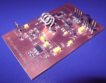
To the right you will find a pic showing the assembly of all components on the same board.
This is how the real board should look when you are going to solder the components.
It is a board made for surface mounted components, so the cuppar is on the top layer.
I am sure you can still use hole mounted components as well.
Grey area is cuppar and each component is draw in different colours all to make it easy to identify for you.
The scale of the pdf is 1:1 and the picture at right is magnified with 4 times.
Click on the pic to enlarge it.
Assembly
Good grounding is very important in a RF system. I use bottom layer as Ground and I connect it with the top layer at several places ( five via-holes) to get a good grounding.
Drill a small hole through the PCB an solder a wire in each via-hole to connect the top layer with the bottom layer which is the ground layer.
The five via-holes can easy be found on the PCB and in the assembly pic at right, they are labelled "GND" and marked with red colour.
Powerline:
Next step is to connect the power.
Add V1 (78L05), C13, C14, C20, C21
Reference oscillator VCTCXO 16.8 MHz.
Next step is to get the reference crystal oscillator running.
Add the VCTCXO (16.8MHz), C22, R5, R6. Test:
Connect the main power and make sure you have +5V volt after V1.
Connect an oscilloscope or frequency meter to pin3 of the VCTCXO and make sure you have an oscillation of 16.8MHz.
VCO:
Next step is to make sure the oscillator start to oscillate.
Add Q1, Q2,
L1, L2, L3, L4
D1, D2,
C1, C2, C3, C4, C5, C6, C7, C8, C9, C10, C11, C12, C18, C19,
R7, R8, R9, R10, R11, R12, R13, R14, R15, R16, R17
Now, connect a 50 ohm resistor from RF-out to ground as "dummy" load.
If you don't have a dummy load or an antenna the transistor Q2 will break easy.
When you connect the main power, the oscillator should start oscillate.
You can connect an oscilloscope to the RF output to probe the signal.
Make sure you have 3-4V DC at the junction of R13-R14.
TP is a "test point" which voltage (Vtune) will be set by the PLL circuit.
You can use this output to measure the VCO voltage to test the unit. Since the PLL circuit hasn't been added yet, we can use this TP as input for testing the VCO and the VCO range.
The voltage at TP will set the oscillating frequency.
If you connect TP to ground, the VCO will be oscillating at it's lowest frequency.
If you connect TP to +5V, the VCO will be oscillating at it's highest frequency.
By changing the voltage at TP you can tune the VCO to any frequency in the VCO range.
If you have a radio in the same room you can use it to find the VCO frequency.
At this point there is no modulation of the transmitter, but you will still find the carrier with the FM receiver.
The inductance of L1 will affect the VCO frequency and VCO range very much.
By spacing/compressing L1 you will easy change the VCO frequency.
In my test I temporary connected TP to ground and used my Frequency counter to check
which frequency the VCO was oscillating at. I then spaced/compressed L1 until I got 88MHz.
Since TP was connected to ground I know 88MHz will be the lowest oscillating frequency of the VCO.
I then reconnected TP to +5V and checked the oscillating frequency again. This time I got 108MHz.
If you don't have a frequency counter you can use any FM radio to find the carrier frequency.
At this point the reference oscillator works and so do the VCO.
It is time to add the last components.
PLL:
Add the LMX2322 circuit, C15, C16, C17, R1, R2, R3, R4
The LMX circuit is small so you must be careful soldering it.
Soldering the LMX2322
Here comes the big challenge. Click here to see photo and read how to solder SOIC and smd components.
The circuit is a fine pitch SO-IC circuit and this little bug can make your life miserable.
Don't worry I will explain how to handle it. Use thin lead solder and a clean soldering tool.
I start by fixate one leg on each side of the circuit and makes sure it is correct placed.
Then I solder all other legs and I don't care if there will be any lead bridges.
After that it is time to clean up and for that I use a "wick".
The desoldering wick is a flattened, braided copper sheath looking for all the world like shielding on phono cord (except that the shielding is tinned) without the cord.
I impregnate the wick with some rosin and place it over the legs and bridges of the circuit. The wick is then heated by the soldering iron, and the molten solder flows up the braid by capillary action.
After that, all bridges will be gone and the circuit looks perfect.
You can find wick and rosin at my component page.
More to think about:
It is important that you use a dummy load of 50ohm when you test the unit.
It is important that the varicap is mounted in right direction (see schematic).
It is important that you are careful and accurate when you solder the componets.
Make sure you don't have any tin/lead bridges which short-circuit strip-lines to ground.
How to make an iductors L1
The inductor L1 will set the frequency range:
4 turns will give 70-88 MHz.
3 turns will give 88-108 MHz.
This is how it is made:
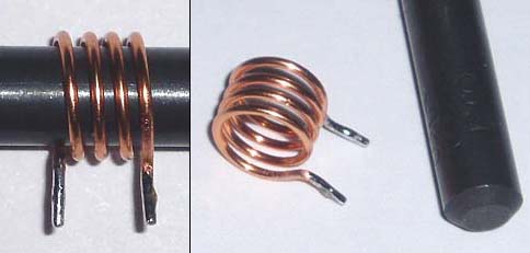
I use enamelled cu wire of 0.8mm. This coil should be 3 turns with a diameter of 6.5mm, so I use a drill of 6.5 mm. (Picture above show a coil of 4 turns!)
First I make a "dummy coil" to measure how long piece of wire it needs. I wrap the wire 3 turns and make the connection pointing straight down and cut the wires.
I then stretch out the "dummy coil" back to a wire to measure how long it was (the wire at top). I take a new wire and make it same length (the wire at bottom).
I use a sharp razor blade to scratch of the enamel at both end of the new straight wire. This new wire is perfect in length and no enamel cover the two ends.
(You have to remove the enamel before you wrapped the cu wire around the drill, else the coil will be bad both in shape and soldering.)
I take the new straight cu wire and wrap it around the drill and make the ends point down. I solder the ends and the coils is ready.
(Picture above show a coil of 4 turns!)
Component support
This project has be constructed to use standard (and easy to find) components.
People often write to me and ask for components, PCB or kits for my projects.
All component for FM PLL controlled VCO unit (Part II) are included in the KIT (Click here to download component list.txt).
Antenna
The antenna part of a transmitter is very important.
Any piece of wire will act as antenna and radiate energy.
The question is how much energy is radiated?
A poor antenna may radiate less then 1% of the transmitted energy, and we do not want that !
There are so many homepages describing antennas so I will only give you a short version here.
The antenna is a tuned unit itself and if it is not properly made, the energy from the transmitter will be reflected (from antenna) back into the RF unit and burn up as heat. Lot of noise will be produced and eventually the heat will destroy the final transistor.
Sine most energy is reflected back into the transmitter, you will not be able to transmit specially long distance either. What we want is a stable system where all energy leaves the antenna out into the air.
A proper antenna is not difficult to build. I suggest a dipole antenna. It is easy to build and work very well.
The basic dipole antenna is of the simplest design, yet most used antenna in the world. The dipole claims a gain of 2.14dbi over isotropic source. The centre conductor goes to one leg of the dipole and the outer conductor (braided wire) goes to the other. The dipole antenna impedance ranges from 36 ohms to 72 ohms depending upon the transmission line used, with 52 ohms as the norm. Separation of the centre and outer conductor where the coax or other feedline connect should not extend beyond 1" inch. Always mount the dipole at least it's total length, or greater height above the ground or building for best results.
Frequency versus length
A dipole is cut to length according to the formula l=468/f(Mhz). Where l is the length in feet and f is the center frequency. The metric formula is l=143/f(Mhz), where l is the length in meters. The length of the dipole antenna is about 80% of an actual half wave at the speed of light in free space. This is due to the Velocity of propagation of electricity in wire versus electromagnetic radiation in free space.
Dipole with Baluns
A dipole antenna is called to be symmetrical. The coax cable is unsymmetrical.
You should not connect an unsymmetrical coax directly to the symmetrical dipole antenna because the outer shield of the coax will act as a third antenna rod and it will affect the antenna (and antenna pattern) in bad ways.
You can say that the coax acting as a radiator instead of the antenna. RF can be induced into other electronic equipment near the radiating feedline, causing RF interference. Furthermore, the antenna is not as efficient as it could be because it is radiating closer to the ground and its radiation (and reception) pattern may be distorted asymmetrically. At higher frequencies, where the length of the dipole becomes significantly short as compared to the diameter of the feeder coax, this becomes a more significant problem. One solution to this problem is to use a balun.
So what is a balune then?
A balun, pronounced /'bæl.?n/ ("bal-un"), is a passive device that converts between balanced and unbalanced electrical signals, such as between coaxial cable and antenna.
Several type of baluns are commonly used with dipoles - current baluns and coax baluns.
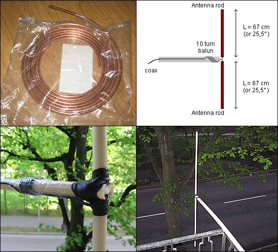
Two simple balun are ferrite and inductive coiled cable, see pic at right.
The inductive coiled balun is simple to make.
A few turns of the cable around a tube will do the job.(It doesn't need to be a ferrite core)
The balun should be placed close to the antenna.
Some links: What is a Balun, and Do I Need One? Balun 1 Balun 2 Balun 3 Balun 4
By now, I think your brain feels pretty "unsymmetrical"... Take a break with a good cup of coffee or tea.
Tuning and testing There is four capacitors C11 to C14 you have to tune for best performance.
A simple way to test the amplifier is to build an extra dipole antenna and use it as a receiver.
Take a look at the schematic at right. I use a dipole antenna as receiving antenna and the signal is then rectified to a DC voltage by the germanium diode and the 10nF cap.
An 100uA -meter will then show the signal strength. A very easy unit to build.
You can remove the 100k resistor and the OP, and connect the uA meter directly after the diode.
The unit will not be so sensitive then, but still work good.
I place the receiving antenna a bit away from the transmitting antenna and tune (C11 to C14) until I reach strongest reading from the 100uA meter. If you get too strong reading you can add a serial resistor to the uA meter or move it farther away. If you get to low signal you can use the OP and set high gain with the 10k pot.
You can also add a (MSA-0636 Cascadable Silicon Bipolar MMIC Amplifiers) between the antenna and the rectifier.
Of course you can tune your system with a dummy load or wattmeter, but I prefer to tune my system with the real antenna connected.
In that way I tune the power amplifier and measure the real field strength with my second antenna.
One basic rule during tuning is to measure the main current to the amplifier.
When the transmitter is close to match (tuned correct) the main current starts to drop, and you will still have high field strength. The field strength can even increase when the main current drops. Then you know the match is good, because most of the energy is going out of the antenna and not reflected back into the amplifier.
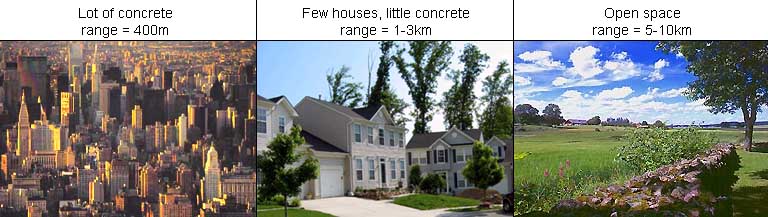
How far will it transmit?
This question is very hard to answer. The transmitting distance is very dependent on the environment around you. If you live in a big city with lot of concrete and iron, the transmitter will probably reach about 400m. If you live in smaller city with more open space and not so much concrete and iron your transmitter will reach much longer distance, up to 3km. If you have very open space you will transmit up to 10km.
One basic rule is to place the antenna at a high and open position. That will improve your transmitting distance quit a lot.
How to build a dipole antenna in 45 minutes
I will explain how to build a simple but very good dipole antenna, and it only took 45 minutes to build.
The antenna rod is made of 6mm copper tube I found in a shop for cars. It is actually tubes for the breaks, but the tube works great as antenna rods.
You can use all kinds of tubes or wire. The benefit of using a tube, is that it is strong and the wider tube diameter you use, the wider frequency range (bandwidth) you will also get. I have noticed that the transmitter gives highest output power around 104-108 MHz so I set my transmitter to 106 MHz.
The calculation gave the rod length of 67 cm. So I cut off two rods at 67cm each. I also found plastic tube to hold the rods and to give it a more stable construction.
I use one plastic tube as boom and a second to contain the two rods. You can see how I used black duct tape to hold the two tubes together.
Inside the vertical tube are the two rods and I have connected a coax to the two rods. The coax is twisted 10 turns around the horizontal tube to form a balun (rf choke) to prevent reflections. This is a poor mans balun and lot of improvement can be done here.
I placed the antenna on my balcony and connected it to the transmitter and turned on power supply. I live in a medium city so I took my car and drove away to test the performance. The signal was perfect with crystal clear stereo audio. There are many concrete building around my transmitter which affects the transmitting range.
The transmitter worked up to 5 km distance when the sight was clear (could not obtain line-in-sight). In city environment it reached 1-2km, due to heavy concrete.
I find this performance very good for a 1W amplifier with an antenna which took me 45 min to build. One should also take in account that the FM signal is Wide FM, which consume much more energy than a narrow FM signal does. All together, I was very pleased with the result.
Antenna testing and measuring
The pic below show you the performance of this antenna.
Thanks to a complex antenna analyser, I have been able to get a plot of the antenna performance.
The red curve show the SWR and the grey show Z (impedance). What we want is a SWR of 1 and Z to be close match to 50 ohm.
As you can see, the best match for this antenna is at 102 MHz where we have SWR = 1.13 and Z = 53 ohm.
I did run my antenna at 106 MHz, where the match is worse SWR = 1.56 and Z = 32 ohm. Conclusion: My antenna was not perfect for 106 MHz, I should re-run my filed test at 102 MHz. I will probably get better results and longer transmitting distance.
Or I should make the antenna a bit shorter to match the frequency 106MHz. (I am sure I will come back to this topic with more measurements and tests, although I am impressed of the transmitter performance even when the antenna was poor.)
Frequency
SWR
Z (imp)
102.00 MHz
1.13
53.1
106.00 MHz
1.56
32.2
Special modification of the VCO
This modification is only needed if you want to extend the VCO range!
The VCO is based around Q1 and the VCO range is from 88 to 108 MHz.
If transistor Q1 is changed to FMMT5179 (you find on my component page) the VCO range will change dramatically. This is becasue the FMMT5179 has very low internal capacitances.
The inductor L1 will set the frequency range:
3 turns will give 100-150 MHz.
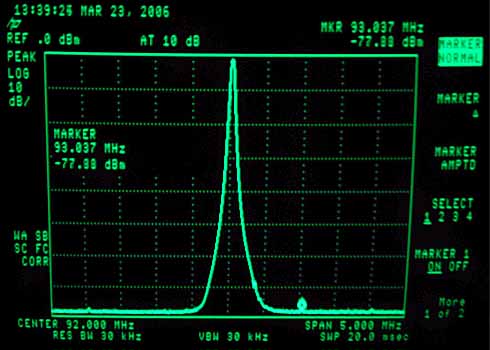
Spectrum Analyzer
Marco from Switzerland is lucky to have access to a Spectrum Analyzer. He was kind to send me this great measurement of the RF unit.
He also gave me some great tip, thanks a lot. Well, the the photo speaks for itself :-)
Final word
This part II describes the FM PLL controlled VCO unit.
Again, this is a strictly educational project explaining how a RF amplifier can be built.
According to the law it is legal to build them, but not to use them.

 Powerline:
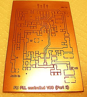 TP is a "test point" which voltage (Vtune) will be set by the PLL circuit.
 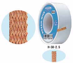 Soldering the LMX2322
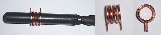

 The antenna is a tuned unit itself and if it is not properly made, the energy from the transmitter will be reflected (from antenna) back into the RF unit and burn up as heat. Lot of noise will be produced and eventually the heat will destroy the final transistor.
 There is four capacitors C11 to C14 you have to tune for best performance.