This article provides an embedded Ethernet digital voice broadcasting system solution, which can easily realize the regional broadcasting function of the broadcasting system. The system is based on the arm architecture and adopts the method of system playback terminal arbitration to control the realization of regional broadcast, and the broadcast content can be played and saved simultaneously.
The Ethernet digital voice broadcasting system mainly refers to the broadcasting system that uses Ethernet as the transmission medium to provide audio services. Ethernet can be used to solve the problem of long-distance transmission of voice signals. Allows designers to create a large-scale network structure to realize the transmission of thousands of digital voice signals on the Ethernet, making full use of existing network resources, avoiding the trouble of repeatedly setting up lines, and realizing the integration of broadcasting and computer networks. It solves the problems of poor sound quality, susceptibility to interference, complex maintenance and management, and poor interaction in traditional broadcasting systems. At the same time, it is possible to select all, part or specific areas for directional group broadcasting, which breaks through the limitation that traditional broadcasting systems can only perform public broadcasting for all areas. Existing Ethernet digital voice broadcasting systems mostly use control signals to control the broadcasting terminal to join or leave the multicast group in realizing the regional broadcasting function. It is necessary to send a control signal to make the terminal join the multicast group before broadcasting can be realized. , Or establish a complex mapping table on the server side to maintain the state of the playback terminal to achieve regional broadcasting, which is more complicated to implement.
1 Structural design
This system adopts C/S structure, is made up of two parts of broadcast system server end and broadcast system broadcast terminal, as shown in Fig. 1.
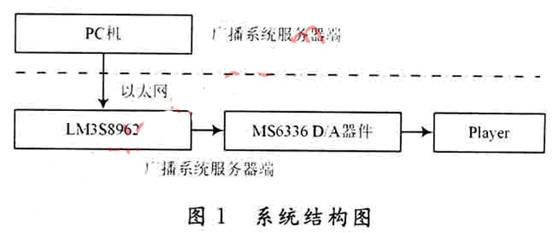
The server of the broadcast system is implemented on a PC, and it is a program of voice signal collection, storage, and network transmission realized by VC++. This part collects and stores the voice signal through a microphone, and then transmits the voice data to the Ethernet via UDP to realize the network transmission function of voice data.
The broadcast system playback terminal is an embedded terminal based on LM3S8962, which can receive the IP voice data packets sent to it from the Ethernet, and the audio decoding chip MS6336 completes the digital/analog conversion and playback of the voice data
2 Broadcast system broadcast terminal hardware design
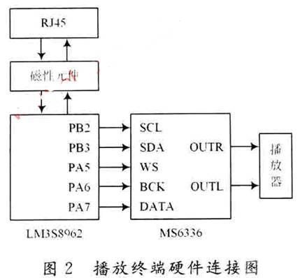
The main control chip of the broadcast system broadcast terminal adopts the microcontroller LM3S8962 provided by LuminaryMicro. This series of chips is the first ARM CortexTM-M3-based controller with an internal integrated Ethernet controller. It is the industry's first ARM chip that supports Industrial Ethernet (IEEE) and can easily implement network functions.
The audio decoder chip uses the MS6336 chip produced by MOSA. The chip is a 16-bit stereo audio digital-to-analog converter, and the supported digital input formats are Right Justifl-ed, Left Justified, I2S. MS6336 control interface adopts I2C bus, the interface is easy to set. The DAC part has accurate and stable current, combined with an excellent symmetrical decoding method, can reproduce high-quality audio signals.
The main control chip LM3S8962 is connected to the RJ45 interface through magnetic components, and is used to receive voice data from the Ethernet. LM3S8962 provides control signals and voice data signals for the audio decoder chip MS6336. LM3S8962 supports I2C function. PB2 and PB3 ports provide I2C clock and data signals respectively. These two pins can be directly connected to the I2C function pins of MS6336, and a pull-up resistor is required. LM3S8962 does not support the data input format required by MS6336. The data input format of MS6336 in the system adopts I2S. Therefore, to provide voice data to MS6336, it is necessary to use GPIO port software of LM3S8962 to simulate the I2S data input format required by MS6336. In the design, PA5, PA6, and PA7 ports are used to simulate this function. The three pins correspond to the I2S channel selection signal, clock signal and data signal respectively. Connect these three pins to the I2S function pin of MS6336.
The hardware structure of the playback terminal of the Ethernet digital voice broadcasting system is shown in Figure 2.
3 Broadcasting system software design
The broadcasting system software is divided into two parts: broadcasting system server software and broadcasting terminal software.
This design realizes the real-time playback of voice data, so the real-time performance of voice data transmission is required to be guaranteed, but the requirements for data integrity are not too strict, and a small amount of packet loss will not affect the overall playback effect, so the voice data of the system The transmission adopts UDP transmission mode. At the same time, the system works in the local area network and there are few temporary users. Therefore, the static IP address allocation is adopted to simplify the realization of the playback terminal software.
3.1 The collection, storage and transmission of voice data on the server side of the broadcasting system
The collection of voice data is implemented using low-level WAVE audio API functions. In order not to cause the loss of voice data, the design uses double buffering to store voice data. The implementation process is shown in Figure 3.
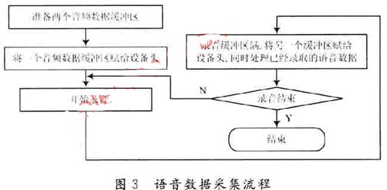
When one recording buffer is full, the system immediately sends another recording buffer to the recording device to continue recording, and the application program should read the data in the full recording buffer and process it. Then call the waveInAddBuffer function to re-assign the buffer to the recording device for recycling.
In order to prevent the loss of voice data in the recording process, it is not enough to simply use double buffering. It should also be noted that when one buffer is full, the application will process the data in the buffer and the second The buffer is used for recording, and the data processing time must be less than the time required for the second buffer to be fully recorded, otherwise the first buffer has not been re-assigned to the recording device after the second buffer is full, which will cause Loss of voice data. When the sample rate of the voice signal is large, increasing the size of the buffer appropriately can effectively solve this problem.
In order to save the broadcast content for later use, it is necessary to save the broadcast content in a WAV file. WAV files have a fixed header format. Before saving voice data, you need to set the header of the WAV file, otherwise the saved WAV file cannot be played. Every time the recording buffer is full, first find the end of the WAV file, and then write the collected data at the end of the file in turn. When the entire broadcast process is over, all the voice data are saved in the WAV file, realizing the storage of voice data.
When a recording buffer is full, it is necessary to send the collected voice data through the network. In the design, first use the Csocket class to create a socket, and then only need to encapsulate the collected data into an IP packet and send it out. The sampling rate of the voice signal in this design is 44.1 kHz, 16-bit dual-channel. In order to avoid the loss of voice data, the size of the recording buffer is set to 1024B.
3.2 Realization of regional broadcasting
An important application of the Ethernet digital voice broadcasting system is not only to realize the whole area broadcasting, but also to realize the local broadcasting function, that is, to broadcast to the designated terminal. Therefore, the UDP multicast packet is used for data transmission in the network transmission of voice IP data packets. Using multicast packets to transmit data, all terminals included in the group in the local area network can receive the data, realizing the whole area broadcast. In order to realize the local broadcast function, a structure is added in front of the voice data in the design, as shown below, and a configuration file is used to store the IP address of each terminal of the system.
02 Broadcasting system broadcast terminal hardware design
The main control chip of the broadcast system broadcast terminal adopts the microcontroller LM3S8962 provided by LuminaryMicro. This series of chips is the first ARM CortexTM-M3-based controller with an internal integrated Ethernet controller. It is the industry's first ARM chip that supports Industrial Ethernet (IEEE) and can easily implement network functions.
The audio decoder chip uses the MS6336 chip produced by MOSA. The chip is a 16-bit stereo audio digital-to-analog converter, and the supported digital input formats are Right Justifl-ed, Left Justified, I2S. MS6336 control interface adopts I2C bus, the interface is easy to set. The DAC part has accurate and stable current, combined with an excellent symmetrical decoding method, can reproduce high-quality audio signals.
The main control chip LM3S8962 is connected to the RJ45 interface through magnetic components, and is used to receive voice data from the Ethernet. LM3S8962 provides control signals and voice data signals for the audio decoder chip MS6336. LM3S8962 supports I2C function. PB2 and PB3 ports provide I2C clock and data signals respectively. These two pins can be directly connected to the I2C function pins of MS6336, and a pull-up resistor is required. LM3S8962 does not support the data input format required by MS6336. The data input format of MS6336 in the system adopts I2S. Therefore, to provide voice data to MS6336, it is necessary to use GPIO port software of LM3S8962 to simulate the I2S data input format required by MS6336. In the design, PA5, PA6, and PA7 ports are used to simulate this function. The three pins correspond to the I2S channel selection signal, clock signal and data signal respectively. Connect these three pins to the I2S function pin of MS6336.
The hardware structure of the playback terminal of the Ethernet digital voice broadcasting system is shown in Figure 2.
3 Broadcasting system software design
The broadcasting system software is divided into two parts: broadcasting system server software and broadcasting terminal software.
This design realizes the real-time playback of voice data, so the real-time performance of voice data transmission is required to be guaranteed, but the requirements for data integrity are not too strict, and a small amount of packet loss will not affect the overall playback effect, so the voice data of the system The transmission adopts UDP transmission mode. At the same time, the system works in a local area network with fewer temporary users. Therefore, static IP address allocation is adopted to simplify the realization of the playback terminal software.
3.1 The collection, storage and transmission of voice data on the server side of the broadcasting system
The collection of voice data is implemented using low-level WAVE audio API functions. In order not to cause the loss of voice data, the design uses double buffering to store voice data. The implementation process is shown in Figure 3.
When one recording buffer is full, the system immediately sends another recording buffer to the recording device to continue recording, and the application program should read the data in the full recording buffer and process it. Then call the waveInAddBuffer function to re-assign the buffer to the recording device for recycling.
In order to prevent the loss of voice data in the recording process, it is not enough to simply use double buffering. It should also be noted that when one buffer is full, the application will process the data in the buffer and the second The buffer is used for recording, and the data processing time must be less than the time required for the second buffer to be fully recorded, otherwise the first buffer has not been re-assigned to the recording device after the second buffer is full, which will cause Loss of voice data. When the sample rate of the voice signal is large, increasing the size of the buffer appropriately can effectively solve this problem.
In order to save the broadcast content for later use, it is necessary to save the broadcast content in a WAV file. WAV files have a fixed header format. Before saving voice data, you need to set the header of the WAV file, otherwise the saved WAV file cannot be played. Every time the recording buffer is full, first find the end of the WAV file, and then write the collected data at the end of the file in turn. When the entire broadcast process is over, all the voice data are saved in the WAV file, realizing the storage of voice data.
When a recording buffer is full, it is necessary to send the collected voice data through the network. In the design, first use the Csocket class to create a socket, and then only need to encapsulate the collected data into an IP packet and send it out. The sampling rate of the voice signal in this design is 44.1 kHz, 16-bit dual-channel. In order to avoid the loss of voice data, the size of the recording buffer is set to 1024B.
3.2 Realization of regional broadcasting
An important application of the Ethernet digital voice broadcasting system is not only to realize the whole area broadcasting, but also to realize the local broadcasting function, that is, to broadcast to the designated terminal. Therefore, the UDP multicast packet is used for data transmission in the network transmission of voice IP data packets. Using multicast packets to transmit data, all terminals included in the group in the local area network can receive the data, realizing the whole area broadcast. In order to realize the local broadcast function, a structure is added in front of the voice data in the design, as shown below, and a configuration file is used to store the IP address of each terminal of the system.
struct STRING
{String IPNO1;
String IPNO2;
…
String IPNO9;
String IPNO10};
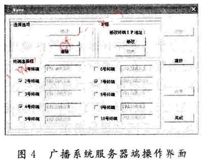
When it is necessary to perform regional broadcasting on certain terminals, select the corresponding numbers of these terminals on the panel of the server side of the broadcasting system (as shown in Figure 4). At this time, the IP address of the selected terminal is read from the configuration file and assigned to the corresponding variable in the structure. When the terminal receives an IP multicast packet, it first judges whether the structure has the same variable as its own IP address, if there is, then the data is received and played, if not, the data is discarded, thus realizing the area Broadcast function. Compared with the method of using a control signal to control the playback terminal to join or leave the multicast group, or to dynamically maintain a complex mapping table to implement the regional broadcast function. This method does not need to interactively control the playback terminal before each broadcast, nor does it need to dynamically track the state of the terminal. It only needs to write the terminal's corresponding IP address into the configuration file when the terminal joins the system for the first time. The function is simple to implement .
3.3 The realization of broadcast system broadcast terminal software
The broadcast system broadcast terminal is divided into two parts to realize, the audio data receiving part is used to receive the voice data and store and forward, and the audio decoder realizes the D/A conversion and playback of the voice signal. The audio data receiving part adopts Socket programming to receive voice data from the Ethernet. After receiving the voice data packet, it must first judge whether the data packet is for itself. The terminal compares the member variable of the structure struct STRING in the IP packet with its own IP address, and if any member variable is equal to its own IP address, it stores the data in the packet, otherwise discards it.
The voice data is received and stored in a circular queue. Due to the disorder of UDP data transmission, the voice data packets need to be sorted after the voice data is received at the voice data receiving end to ensure the sequential processing of the voice data and the correct restoration Voice signal. At the same time, in order to avoid network jitter, the data is processed every time when there are at least 5 packets in the circular queue.
The data input format of MS6336 in the design adopts I2S format. Because LM3S8962 does not support this data format, software simulation is adopted to realize I2S function through GPIO port. In order to completely restore the voice signal, it is necessary to ensure that the timing of the I2S signal is strict and accurate, and the conversion between high and low levels is implemented by a delay program. The I2S timing diagram is shown in Figure 5.
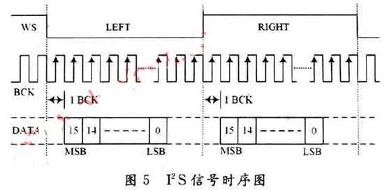
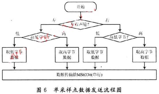
The broadcast system broadcast terminal clock frequency is 40 MHz, and the time to send each data bit is 600 ns calculated from the sampling rate. LM3S8962 provides voice data to MS6336, and realizes serial transmission through GPIO port according to sampling point. Each sampling point contains four bytes, and the data sending process of a sampling point is shown in Figure 6.
4 Result analysis
The size of the voice data packet transmitted by the system via Ethernet is 1024B. In order to avoid network jitter, the terminal starts broadcasting when receiving 5 data packets. The broadcasting delay time is about 30 ms, which meets the functional indicators. The server side can control the work of 10 broadcasting terminals at the same time. By selecting the corresponding terminal number on the server side, the whole area broadcasting and local broadcasting functions of the broadcasting system can be successfully realized.
5 Conclusion
Starting from actual needs, we design and implement an Ethernet digital voice broadcasting system. The experimental results show that the system's playback terminal decides whether to perform voice broadcasting to realize regional broadcasting is a simple and effective way to realize global broadcasting and regional broadcasting of voice signals. The system player terminal adopts GPIO port software simulation to realize the I2S function, which can accurately realize the I2S timing, complete the data transmission of the voice signal, and realize the real-time broadcast of the voice signal. The design structure is reasonable, and can easily realize the expansion of functions, such as timing broadcast, music playback, remote management, real-time monitoring, etc. This design has important practical significance and provides a foundation for solving large and complex Ethernet broadcast systems.
Our other product:


