SPI, I2C, UART, I2S, GPIO, SDIO, CAN, just read this article
The bus always gets stuck in it. The signals in this world are all the same, but there are thousands of buses, which is a headache. Generally speaking, there are three kinds of buses: internal bus, system bus and external bus. The internal bus is the bus between the peripheral chips in the microcomputer and the processor, which is used for the interconnection at the chip level; while the system bus is the bus between the plug-in boards and the system board in the microcomputer, and is used for the mutual exchange at the plug-in board level. The external bus is the bus between the microcomputer and the external device. As a device, the microcomputer exchanges information and data with other devices through the bus. It is used for device-level interconnection.
In addition to the bus, there are also some interfaces, which are a collection of multiple buses, or they are not rejected.
1. SPI
SPI (Serial Peripheral Interface): The synchronous serial bus method proposed by MOTOROLA. High-speed synchronous serial port. 3 to 4 wire interface, independent sending and receiving, can be synchronized.

It is widely used because of its powerful hardware functions. In the intelligent instrument and measurement and control system composed of single chip microcomputer. If the speed requirement is not high, the SPI bus mode is a good choice. It can save I/O ports, improve the number of peripherals and the performance of the system. The standard SPI bus consists of four lines: serial clock line (SCK), master input/slave output line (MISO). Master output/slave input line (MOSI) and chip select signal (CS). Some SPI interface chips have interrupt signal lines or do not have MOSI.
The SPI bus consists of three signal lines: serial clock (SCLK), serial data output (SDO), and serial data input (SDI). The SPI bus can realize the interconnection of multiple SPI devices. The SPI device that provides the SPI serial clock is an SPI master or master device (Master), and other devices are SPI slaves or slave devices (Slave). Full-duplex communication can be realized between master and slave devices. When there are multiple slave devices, a slave device selection line can be added. If you use a universal IO port to simulate SPI bus, you must have an output port (SDO), an input port (SDI), and the other port depends on the type of device implemented. If you want to implement a master-slave device, you need an input and output port. , If only the master device is realized, the output port is enough; if only the slave device is realized, only the input port is required.
2. I2C
I2C (Inter-Integrated Circuit): A two-wire serial bus developed by PHILIPS, used to connect microcontrollers and their peripheral devices.
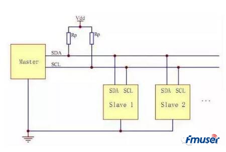
The I2C bus uses two wires (SDA and SCL) to transfer information between the bus and the device, serial communication between the microcontroller and external devices, or two-way data transfer between the master device and the slave device. I2C is OD output, most of I2C are 2-wire (clock and data), generally used to transmit control signals.
I2C is a multi-master bus, so any device can work like a master and control the bus. Each device on the bus has a unique address, and according to their own capabilities, they can work as transmitters or receivers. Multiple microcontrollers can coexist on the same I2C bus.
3. UART
UART: Universal asynchronous serial port, complete two-way communication according to standard baud rate, slow speed.
The UART bus is an asynchronous serial port, so it is generally much more complicated than the first two synchronous serial ports. Generally, it consists of a baud rate generator (the generated baud rate is equal to 16 times the transmission baud rate), UART receiver, and UART transmitter. It consists of two wires in hardware, one for sending and one for receiving.
UART is a chip used to control computers and serial devices. One thing to note is that it provides an RS-232C data terminal device interface so that the computer can communicate with modems or other serial devices that use the RS-232C interface. As part of the interface, UART also provides the following functions:
The parallel data transmitted from the computer is converted into the output serial data stream. Convert serial data from outside the computer into bytes for use by devices that use parallel data inside the computer. Add a parity bit to the output serial data stream, and perform a parity check on the data stream received from the outside. Add the start-stop mark to the output data stream, and delete the start-stop mark from the received data stream. Handle the interrupt signal sent by the keyboard or mouse (the keyboard and mouse are also serial devices). Can handle the synchronization management problem of the computer and the external serial device. Some high-end UARTs also provide buffers for input and output data. The newer UART is 16550, which can store 16 bytes of data in the buffer before the computer needs to process the data. The usual UART is 8250. Now if you buy a built-in modem, there will usually be a 16550 UART inside the modem.
3. Comparison of SPI, I2C and UART
Both SPI and I2C communication methods are short-distance communication between the chip and the chip or between other components such as the sensor and the chip. SPI and IIC are board-to-board communication, IIC sometimes also does board-to-board communication, but the distance is very short, but more than one meter, for example, some touch screens, mobile phone LCD screens, many thin film cables use IIC, I2C can be used to replace standard parallel Bus, various integrated circuits and functional modules that can be connected. I2C is a multi-master bus, so any device can work like a master and control the bus. Each device on the bus has a unique address, and according to their own capabilities, they can work as transmitters or receivers. Multiple microcontrollers can coexist on the same I2C bus. These two lines belong to low-speed transmission.
The UART is used in the communication between two devices, such as the communication between a device and a computer made with a single-chip microcomputer. Such communication can be done over long distances. The UART speed is faster than the above two, up to about 100K. It is used to communicate with the computer and the device or between the computer and the calculation, but the effective range will not be very long, about 10 meters. The advantage of the UART is that it has a wide range of support and a program design structure. Quite simply, with the development of USB, UART is gradually going downhill.
5. I2S
I2S (Inter-IC Sound Bus) is a bus standard developed by Philips for audio data transmission between digital audio devices. Most of it is 3-wire (in addition to clock and data, there is also a left and right channel selection signal), I2S is mainly used to transmit audio signals. Such as STB, DVD, MP3, etc. commonly used.

In the I2S standard, both the hardware interface specification and the format of digital audio data are specified. I2S has 3 main signals: 1) Serial clock SCLK, also called bit clock (BCLK), that is, corresponding to each bit of digital audio data, SCLK has 1 pulse. The frequency of SCLK = 2 × sampling frequency × number of sampling bits. 2) The frame clock LRCK, (also called WS), is used to switch the data of the left and right channels. LRCK of "1" means that the data of the left channel is being transmitted, and "0" means that the data of the right channel is being transmitted. The frequency of LRCK is equal to the sampling frequency. 3) The serial data SDATA is the audio data expressed in twos complement. Sometimes in order to better synchronize the systems, another signal MCLK is needed to be transmitted, called the master clock, also called the system clock (Sys Clock), which is 256 times or 384 times the sampling frequency.
6. GPIO
GPIO (General Purpose Input Output) or bus expander, using industry standard I2C, SMBus or SPI interface to simplify the expansion of I/O ports.
When the microcontroller or chipset does not have enough I/O ports, or when the system needs to use remote serial communication or control, GPIO products can provide additional control and monitoring functions. Each GPIO port can be configured as input or output by software. Maxim's GPIO product line includes 8-port to 28-port GPIO, providing push-pull output or open-drain output. Available in a miniature 3mm x 3mm QFN package.
(1) The advantages of GPIO (port expander):
① Low power consumption: GPIO has lower power consumption (about 1μA, while the working current of μC is 100μA).
② Integrated IIC slave interface: GPIO built-in IIC slave interface, it can work at full speed even in standby mode.
③ Small package: GPIO devices provide the smallest package size-3mm x 3mm QFN!
④ Low cost: You don't have to pay for unused functions!
⑤ Quick listing: no need to write additional codes, documents, and no maintenance work!
Flexible lighting control: Built-in multiple high-resolution PWM outputs.
⑥ Predeterminable response time: shorten or determine the response time between external events and interrupts.
⑦ Better lighting effect: matched current output to ensure uniform display brightness.
⑧ Simple wiring: only 2 IIC buses or 3 SPI buses are required
7. SDIO
SDIO is an SD-type expansion interface. In addition to being able to connect to an SD card, it can also be connected to devices that support the SDIO interface. The purpose of the socket is not only to insert a memory card. PDAs and laptops that support the SDIO interface can be connected to GPS receivers, Wi-Fi or Bluetooth adapters, modems, LAN adapters, barcode readers, FM radios, TV receivers, radio frequency authentication readers, Or digital cameras and other devices that use SD standard interfaces.
The SDIO protocol is evolved and upgraded from the protocol of the SD card. Many places retain the read and write protocol of the SD card. At the same time, the SDIO protocol adds the CMD52 and CMD53 commands to the SD card protocol. Because of this, an important difference between SDIO and SD card specifications is the addition of low-speed standards. The target application of low-speed cards starts with the smallest hardware to support low-speed I/O capabilities. Low-speed cards support applications such as modems, barcode scanners and GPS receivers. High-speed cards support network cards, TV cards and "combo" cards, etc. Combination cards refer to memory + SDIO.
Another important difference between SDIO and SD card SPEC is the addition of low-speed standards. SDIO card only needs SPI and 1-bit SD transmission mode. The target application of low-speed cards is to support low-speed I/O capabilities with minimal hardware expenditure. Low-speed cards support applications such as MODEMs, bar scanners and GPS receivers. For combination cards, full speed and 4BIT operation are mandatory requirements for the internal memory and SDIO part of the card. In non-combined SDIO devices, the maximum speed must only reach 25M, and the maximum speed of the combined card is the same as the maximum speed of the SD card, which is higher than 25M.
8. CAN
CAN, the full name is "Controller Area Network", that is, the Controller Area Network, which is one of the most widely used field buses in the world. Initially, CAN was designed as a microcontroller communication in the automotive environment, exchanging information between the various electronic control devices ECU in the vehicle, forming an automotive electronic control network. For example, CAN control devices are embedded in engine management systems, transmission controllers, instrumentation equipment, and electronic backbone systems.
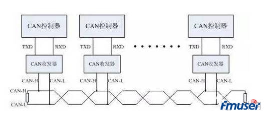
In a single network composed of CAN bus, in theory, countless nodes can be connected. In practical applications, the number of nodes is limited by the electrical characteristics of the network hardware. For example, when using Philips P82C250 as a CAN transceiver, 110 nodes are allowed to be connected in the same network. CAN can provide up to 1Mbit/s data transmission rate, which makes real-time control very easy. In addition, the hardware's error verification feature also enhances CAN's ability to resist electromagnetic interference.
Features of CAN bus:
1) It can work in a multi-master mode. Any node on the network can actively send information to other nodes on the network at any time, regardless of master and slave, and the communication mode is flexible.
2) The nodes on the network can be divided into different priorities to meet different real-time requirements.
3) A non-destructive bit arbitration bus structure mechanism is adopted. When two nodes transmit information to the network at the same time, the node with lower priority actively stops data transmission, while the node with higher priority can continue to transmit data without being affected.
4) Data can be received in several transmission modes: point-to-point, point-to-multipoint and global broadcast.
5) The maximum direct communication distance can reach 10km (speed below 4Kbps).
6) The communication rate can reach up to 1MB/s (the longest distance is 40m at this time).


|
|
|
|
How far(long) the transmitter cover?
The transmission range depends on many factors. The true distance is based on the antenna installing height , antenna gain, using environment like building and other obstructions , sensitivity of the receiver, antenna of the receiver . Installing antenna more high and using in the countryside , the distance will much more far.
EXAMPLE 5W FM Transmitter use in the city and hometown:
I have a USA customer use 5W fm transmitter with GP antenna in his hometown ,and he test it with a car, it cover 10km(6.21mile).
I test the 5W fm transmitter with GP antenna in my hometown ,it cover about 2km(1.24mile).
I test the 5W fm transmitter with GP antenna in Guangzhou city ,it cover about only 300meter(984ft).
Below are the approximate range of different power FM Transmitters. ( The range is diameter )
0.1W ~ 5W FM Transmitter :100M ~1KM
5W ~15W FM Ttransmitter : 1KM ~ 3KM
15W ~ 80W FM Transmitter : 3KM ~10KM
80W ~500W FM Transmitter : 10KM ~30KM
500W ~1000W FM Transmitter : 30KM ~ 50KM
1KW ~ 2KW FM Transmitter : 50KM ~100KM
2KW ~5KW FM Transmitter : 100KM ~150KM
5KW ~10KW FM Transmitter : 150KM ~200KM
How to contact us for the transmitter?
Call me +8618078869184 OR
Email me sky@fmuser.org
1.How far you want to cover in diameter ?
2.How tall of you tower ?
3.Where are you from ?
And we will give you more professional advice.
About Us
FMUSER.ORG is a system integration company focusing on RF wireless transmission / studio video audio equipment / streaming and data processing .We are providing everything from advice and consultancy through rack integration to installation, commissioning and training.
We offer FM Transmitter, Analog TV Transmitter, Digital TV transmitter, VHF UHF Transmitter, Antennas, Coaxial Cable Connectors, STL, On Air Processing, Broadcast Products for the Studio, RF Signal Monitoring, RDS Encoders, Audio Processors and Remote Site Control Units, IPTV Products, Video / Audio Encoder / Decoder, designed to meet the needs of both large international broadcast networks and small private stations alike.
Our solution has FM Radio Station / Analog TV Station / Digital TV Station / Audio Video Studio Equipment / Studio Transmitter Link / Transmitter Telemetry System / Hotel TV System / IPTV Live Broadcasting / Streaming Live Broadcast / Video Conference / CATV Broadcasting system.
We are using advanced technology products for all the systems, because we know the high reliability and high performance are so important for the system and solution . At the same time we also have to make sure our products system with a very reasonable price.
We have customers of public and commercial broadcasters, telecom operators and regulation authorities , and we also offer solution and products to many hundreds of smaller, local and community broadcasters .
FMUSER.ORG has been exporting more than 15 years and have clients all over the world. With 13 years experience in this field ,we have a professional team to solve customer's all kinds of problems. We dedicated in supplying the extremely reasonable pricing of professional products & services. Contact email : sky@fmuser.org
Our Factory
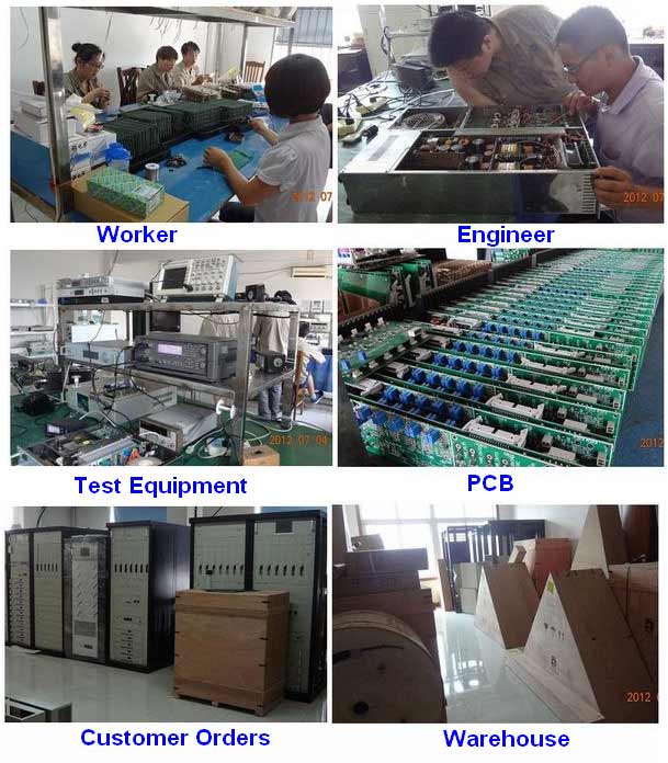
We have modernization of the factory . You are welcome to visit our factory when you come to China.

At present , there are already 1095 customers around the world visited our Guangzhou Tianhe office . If you come to China , you are welcome to visit us .
At Fair
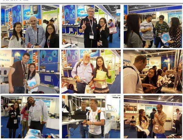
This is our participation in 2012 Global Sources Hong Kong Electronics Fair . Customers from all over the world finally have a chance to get together.
Where is Fmuser ?
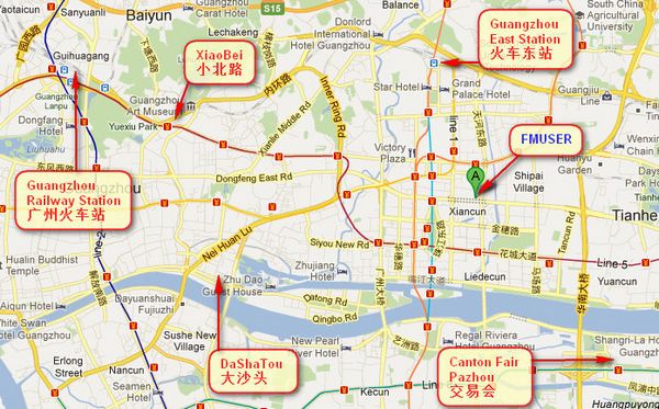
You can search this numbers " 23.127460034623816,113.33224654197693 " in google map , then you can find our fmuser office .
FMUSER Guangzhou office is in Tianhe District which is the center of the Canton . Very near to the Canton Fair , guangzhou railway station, xiaobei road and dashatou , only need 10 minutes if take TAXI . Welcome friends around the world to visit and negotiate .
Contact: Sky Blue
Cellphone: +8618078869184
WhatsApp: +8618078869184
Wechat: +8618078869184
E-mail: sky@fmuser.org
QQ: 727926717
Skype: sky198710021
Address: No.305 Room HuiLan Building No.273 Huanpu Road Guangzhou China Zip:510620
|
|
|
|
English: We accept all payments , such as PayPal, Credit Card, Western Union, Alipay, Money Bookers, T/T, LC, DP, DA, OA, Payoneer, If you have any question , please contact me sky@fmuser.org or WhatsApp +8618078869184
-
PayPal.  www.paypal.com www.paypal.com
We recommend you use Paypal to buy our items ,The Paypal is a secure way to buy on internet .
Every of our item list page bottom on top have a paypal logo to pay.
Credit Card.If you do not have paypal,but you have credit card,you also can click the Yellow PayPal button to pay with your credit card.
---------------------------------------------------------------------
But if you have not a credit card and not have a paypal account or difficult to got a paypal accout ,You can use the following:
Western Union.  www.westernunion.com www.westernunion.com
Pay by Western Union to me :
First name/Given name: Yingfeng
Last name/Surname/ Family name: Zhang
Full name: Yingfeng Zhang
Country: China
City: Guangzhou
|
---------------------------------------------------------------------
T/T . Pay by T/T (wire transfer/ Telegraphic Transfer/ Bank Transfer)
First BANK INFORMATION (COMPANY ACCOUNT):
SWIFT BIC: BKCHHKHHXXX
Bank name: BANK OF CHINA (HONG KONG) LIMITED, HONG KONG
Bank Address: BANK OF CHINA TOWER, 1 GARDEN ROAD, CENTRAL, HONG KONG
BANK CODE: 012
Account Name : FMUSER INTERNATIONAL GROUP LIMITED
Account NO. : 012-676-2-007855-0
---------------------------------------------------------------------
Second BANK INFORMATION (COMPANY ACCOUNT):
Beneficiary: Fmuser International Group Inc
Account Number: 44050158090900000337
Beneficiary's Bank: China Construction Bank Guangdong Branch
SWIFT Code: PCBCCNBJGDX
Address: NO.553 Tianhe Road, Guangzhou, Guangdong,Tianhe District, China
**Note: When you transfer money to our bank account, please DO NOT write anything in the remark area, otherwise we won't be able to receive the payment due to government policy on international trade business.
|
|
|
|
* It will be sent in 1-2 working days when payment clear.
* We will send it to your paypal address. If you want to change address, please send your correct address and phone number to my email sky@fmuser.org
* If the packages is below 2kg,we will be shipped via post airmail, it will take about 15-25days to your hand.
If the package is more than 2kg,we will ship via EMS , DHL , UPS, Fedex fast express delivery,it will take about 7~15days to your hand.
If the package more than 100kg , we will send via DHL or air freight. It will take about 3~7days to your hand.
All the packages are form China guangzhou.
* Package will be sent as a "gift" and declear as less as possible,buyer don't need to pay for "TAX".
* After ship, we will send you an E-mail and give you the tracking number.
|
|
|
For Warranty .
Contact US--->>Return the item to us--->>Receive and send another replace .
Name: Liu xiaoxia
Address: 305Fang HuiLanGe HuangPuDaDaoXi 273Hao TianHeQu Guangzhou China.
ZIP:510620
Phone: +8618078869184
Please return to this address and write your paypal address,name,problem on note: |
|


