Local Area Network (LAN) refers to a computer network that covers a local area and is usually used within an organization.
Compared with a wide area network, a local area network usually has a small physical span and a small number of devices but has high bandwidth requirements.
Compared with the OSI reference model, the local area network technology mainly defines the realization of the physical layer and the data link layer. That is, it defines the physical characteristics of the medium, realizes point-to-point physical addressing and line control functions, and may also include error control, flow control and other functions.
Ring and star are the most common local area network topologies, in addition to bus type and tree type.
Ethernet is currently the most widely used local area network technology. It uses switches for network connection and organization, and uses a star or bus topology.
IEEE802 Reference Model#
Early LAN technologies were developed by various manufacturers and were incompatible with each other. IEEE proposed the 802 series of standards, which promoted the standardization of LAN technologies.
The IEEE802 physical layer defines the transmission media and topology, making it compatible with multiple transmission media such as twisted pair, coaxial cable, optical fiber, and wireless.
Compared with the OSI reference model, IEEE802 divides the functions of the data link layer into two sublayers: Media Access Control (MAC) and Logic Link Control (LLC).
Media Access Control#
The MAC sublayer directly controls the transmission of frames on the channel, providing physical addressing and line control functions. The MAC sublayer accepts data blocks from the LLC layer, and adds a MAC header and tailer to encapsulate them into frames.
The MAC header generally contains the control field, destination MAC address, source MAC address, etc., and the MAC tail generally contains the verification information of the frame.
The core task of the MAC sublayer is to solve the problem of conflicts when different devices in the local area network compete for shared channels.According to the different deployment positions of resource allocation strategies, it is divided into two types: centralized and distributed.
Centralized control uses a controller to allocate channel resources, and any device using the channel must be authorized by the controller.
In a distributed control network, all devices cooperate to perform resource allocation. For example, in a token ring network, a special frame called a token is transmitted on the channel, and only the device that receives the frame can use the channel.
Carrier Sense Multiple Access (CSMA) is a distributed media access control protocol.
CSMA is divided into 3 categories according to the monitoring and sending strategy:
Discontinuous CSMA: When the device monitors that the channel is busy or conflicts, it will wait for a random period of time and then monitor again, and the channel will be sent immediately if the channel is idle. This strategy has a higher delay and a lower channel utilization.
Continuous CSMA: When the device detects that the channel is busy or conflicts, it will always monitor, and if the channel is free, it will send immediately. The channel utilization is high, but more conflicts will occur.
p-Continuous CSMA: The device will always monitor when the channel is busy or conflict. If the channel is free, it will decide whether to send according to the probability p. Continuous CSMA can be regarded as a special case of p-Continuous CSMA: 1-Continuous CSMA
These methods can reduce the occurrence of conflicts, but they cannot completely solve the collision problem. We need to improve the program.
Carrier Sense Multiple Access with Collision Detection (CSMA/CD) requires the device to monitor while sending the frame. If a conflict is detected during the sending process, the conflict processing will be executed:
Suspend data transmission and send an all-one signal as a blocking message, so that other devices can detect the conflict as soon as possible.
Wait for a random period of time within a certain range and then send again
If the conflict occurs again, the truncated binary exponential backoff algorithm is used to send, that is, the waiting time for each time is twice that of the previous time. After 16 attempts, the sending is still failed.
Carrier Sense Multiple Access with Collision Avoidance (CSMA/CA) uses active monitoring to avoid conflicts. There are two main methods to avoid conflicts:
When the channel is idle and the device is ready to send, the device always waits for a random period of time, and then sends data when it finds that the channel is still idle after the waiting. Since the waiting time of each device is randomly generated, the possibility of conflict again is greatly reduced.
The device first sends a small RTS (Request to Send) frame to the nearest access point (Access Point) before sending the frame, and waits for the target to reply with a CTS (Clear to Send) frame before starting to send.
The CSMA/CA scheme was adopted by IEEE802.11. In addition, there are methods such as bit arbitration (BA) and carrier priority (CP).
Logical Link Control#
The logical link control (LLC) sublayer works above the MAC sublayer and provides an interface for network layer access.
The following figure shows the relationship between the layers within a frame:
The LLC layer provides functions such as frame error control and flow control, and LLC provides 3 working modes:
Unconfirmed connectionless service
Connection service
Connectionless service with confirmation
Unacknowledged connectionless service is a service in the form of datagrams, which does not include error control and flow control functions. Because upper-layer software such as TCP provides reliability assurance and flow control functions, unacknowledged connectionless services reduce repetition and increase For efficiency, it is the best choice most of the time.
The connection service is suitable for simple devices without upper-layer network protocol support. It requires the devices to establish a logical connection through handshake and then communicate. It provides reliability assurance and flow control functions.
The connection method requires logical link control software to maintain a large amount of connection data, and it takes time to establish a logical link before communication. In automation control and other occasions, the control host needs to communicate with a large number of embedded controllers, and the communication timeliness and timeliness High reliability requirements.
The connectionless service with confirmation does not establish a logical connection, but requires the receiver to send a confirmation message after receiving the data.
The data transmitted by the LLC protocol is called the Protocol Data Unit (PDU).
Corresponding to the 3 working modes, LLC is divided into three operations:
Type 1 operation: Use unnumbered PDUs to implement connectionless services without confirmation
Type 2 operation: use asynchronous balance mode to support LLC services in connection mode
Type 3 operation: use two unnumbered PDUs to realize connectionless service with confirmation
The three operations all use the same PDU format, and they all consist of 4 fields:
Destination Service Access Point (DSAP), 7bit
Source Service Access Point (SSAP), 7bit
DSAP type, single address or group address, 1bit
PDU type, command PDU or response PDU, 1bit
Type 1 operations use unnumbered (UI) PDUs for communication, without error control and flow control functions.
In the second type of operation, a device first sends a SABME PDU request to establish a logical link. If the target device accepts the request, it sends an unnumbered acknowledgment (AC) PDU, otherwise it sends a DM PDU to refuse the connection.
After the connection is established, all PDUs between the two parties will have a number for sorting, retransmission and flow control. Both parties can send a Disconnect (DISC) PDU at any time to terminate the logical connection.
Compared with the first type of operation, the type 3 operation adds an unnumbered (UC) PDU for reception confirmation.
Internet equipment#
Hubs and bridges#
A hub (HUB) is a common network device in a star topology. It is connected to multiple devices through a twisted pair cable. Frames from one device are sent to all other devices.
The obvious problem with hubs is that every frame is broadcast, occupying a large number of channels.
Bridge is an early attempt to solve this problem.There are two ports on the bridge, which are connected to two subnets that use the same MAC protocol.
There are two tables inside the bridge that store the MAC addresses of all devices in subnets A and B. When the system starts running, these two tables are empty.
At this time, the bridge receives the frame from A and forwards it to B, and adds the source MAC address of the frame to the table of subnet A.
Similar processing is performed on frames from subnet B. After a period of time, the bridge will obtain almost all MAC addresses in subnets A and B.
When a frame is sent from a device in subnet A to the hub, the frame is broadcast to other devices and bridges in A.
When the bridge finds that the destination MAC belongs to subnet A, it directly discards the frame. If the destination address belongs to subnet B, it will be sent to the hub of B for broadcast.
switch#
Now people use Layer 2 switches (Switch) instead of hubs. Switches also use twisted-pair cables to connect to multiple devices.
The switch maintains a MAC port mapping table internally. This table saves the MAC addresses of all devices connected to it and the ports connected to it.The switch reads the destination MAC address of the frame header and sends it to the corresponding port.
Switches are divided into cut-through and store-and-forward switches. The cut-through switches directly send the frame to the target port, and the store-and-forward switch saves the frame and completes the CRC check and error correction before forwarding it.
When the frame comes from an unknown source MAC address, the switch will add the correspondence between the frame port and MAC to the mapping table. If the mapping table is full, the oldest data will be overwritten.
When a frame is sent to an unknown MAC address, the switch will broadcast the frame. If the target of the frame is indeed a device in the network, the frame sent by the device in response will let the switch know its MAC address.
VLAN is another important function of the switch. It divides the devices under a switch into multiple broadcast domains. When broadcasting, it is only sent to the devices in the same broadcast domain.
Router and Layer 3 Switch#
Broadcasting consumes a lot of network traffic, and routers can isolate local areas to form multiple broadcast domains.
The router is the third layer of the working OSI, that is, the device at the network layer. The core function of the router is to send the IP data packet to the next hop routing device according to the destination IP address.
In addition, routers also have strong network layer control functions, such as NAT and DHCP. However, routers rely on software to decide to use CPU forwarding, and the forwarding rate is much lower than that of switches.
If device A wants to send data to B, then A will use the subnet mask to obtain the network address to determine whether the destination IP is in the same network segment as itself. If it is in the same network segment, but does not know the MAC address required to forward the data, A Just send a broadcast ARP request, and B returns its MAC address.
A large number of ARP broadcasts may occur in the above process, so a device is needed to divide the LAN into multiple broadcast domains according to network segments to reduce the channels occupied by broadcasts.
The router can complete this function, but the router forwarding speed is too slow, we need to combine the high speed of the switch hardware exchange.
The three-layer switch is a switch that can read IP packets and perform some routing functions. It has some network layer control functions and hardware-based high-speed forwarding capabilities.
However, the cost of a three-layer switch is relatively high, and it is usually used in a large local area network.
Conflict domain and broadcast domain#
When multiple devices are connected to the same medium, they may conflict due to media grabbing. The range of media conflicts that may occur in the network is called a conflict domain.
It can be seen that the collision domain is a physical layer concept. The two ports of the bridge divide the network into two collision domains. For the switch, each port of it is a collision domain.
The broadcast domain is the reach of the broadcast frame and belongs to the concept of the data link layer. The devices connected to the bridge are generally in a broadcast domain.
The devices on the switch are generally in a broadcast domain, but the VLAN technology of the switch can be divided into multiple broadcast domains.


|
|
|
|
How far(long) the transmitter cover?
The transmission range depends on many factors. The true distance is based on the antenna installing height , antenna gain, using environment like building and other obstructions , sensitivity of the receiver, antenna of the receiver . Installing antenna more high and using in the countryside , the distance will much more far.
EXAMPLE 5W FM Transmitter use in the city and hometown:
I have a USA customer use 5W fm transmitter with GP antenna in his hometown ,and he test it with a car, it cover 10km(6.21mile).
I test the 5W fm transmitter with GP antenna in my hometown ,it cover about 2km(1.24mile).
I test the 5W fm transmitter with GP antenna in Guangzhou city ,it cover about only 300meter(984ft).
Below are the approximate range of different power FM Transmitters. ( The range is diameter )
0.1W ~ 5W FM Transmitter :100M ~1KM
5W ~15W FM Ttransmitter : 1KM ~ 3KM
15W ~ 80W FM Transmitter : 3KM ~10KM
80W ~500W FM Transmitter : 10KM ~30KM
500W ~1000W FM Transmitter : 30KM ~ 50KM
1KW ~ 2KW FM Transmitter : 50KM ~100KM
2KW ~5KW FM Transmitter : 100KM ~150KM
5KW ~10KW FM Transmitter : 150KM ~200KM
How to contact us for the transmitter?
Call me +8618078869184 OR
Email me [email protected]
1.How far you want to cover in diameter ?
2.How tall of you tower ?
3.Where are you from ?
And we will give you more professional advice.
About Us
FMUSER.ORG is a system integration company focusing on RF wireless transmission / studio video audio equipment / streaming and data processing .We are providing everything from advice and consultancy through rack integration to installation, commissioning and training.
We offer FM Transmitter, Analog TV Transmitter, Digital TV transmitter, VHF UHF Transmitter, Antennas, Coaxial Cable Connectors, STL, On Air Processing, Broadcast Products for the Studio, RF Signal Monitoring, RDS Encoders, Audio Processors and Remote Site Control Units, IPTV Products, Video / Audio Encoder / Decoder, designed to meet the needs of both large international broadcast networks and small private stations alike.
Our solution has FM Radio Station / Analog TV Station / Digital TV Station / Audio Video Studio Equipment / Studio Transmitter Link / Transmitter Telemetry System / Hotel TV System / IPTV Live Broadcasting / Streaming Live Broadcast / Video Conference / CATV Broadcasting system.
We are using advanced technology products for all the systems, because we know the high reliability and high performance are so important for the system and solution . At the same time we also have to make sure our products system with a very reasonable price.
We have customers of public and commercial broadcasters, telecom operators and regulation authorities , and we also offer solution and products to many hundreds of smaller, local and community broadcasters .
FMUSER.ORG has been exporting more than 15 years and have clients all over the world. With 13 years experience in this field ,we have a professional team to solve customer's all kinds of problems. We dedicated in supplying the extremely reasonable pricing of professional products & services. Contact email : [email protected]
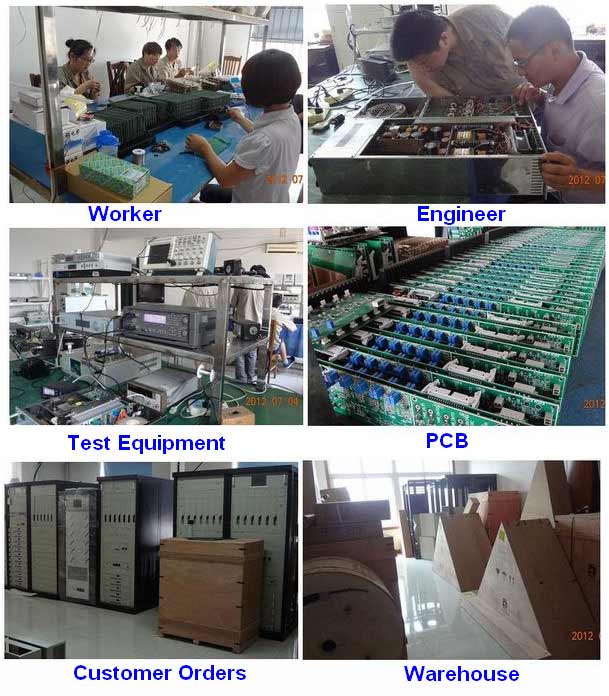
Our Factory

We have modernization of the factory . You are welcome to visit our factory when you come to China.

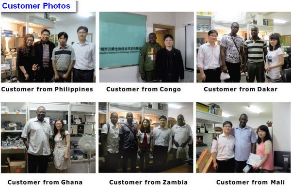
At present , there are already 1095 customers around the world visited our Guangzhou Tianhe office . If you come to China , you are welcome to visit us .
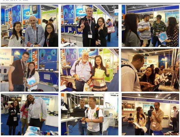
At Fair

This is our participation in 2012 Global Sources Hong Kong Electronics Fair . Customers from all over the world finally have a chance to get together.
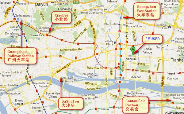
Where is Fmuser ?

You can search this numbers " 23.127460034623816,113.33224654197693 " in google map , then you can find our fmuser office .
FMUSER Guangzhou office is in Tianhe District which is the center of the Canton . Very near to the Canton Fair , guangzhou railway station, xiaobei road and dashatou , only need 10 minutes if take TAXI . Welcome friends around the world to visit and negotiate .
Contact: Sky Blue
Cellphone: +8618078869184
WhatsApp: +8618078869184
Wechat: +8618078869184
E-mail: [email protected]
QQ: 727926717
Skype: sky198710021
Address: No.305 Room HuiLan Building No.273 Huanpu Road Guangzhou China Zip:510620
|
|
|
|
English: We accept all payments , such as PayPal, Credit Card, Western Union, Alipay, Money Bookers, T/T, LC, DP, DA, OA, Payoneer, If you have any question , please contact me [email protected] or WhatsApp +8618078869184
-
PayPal.  www.paypal.com www.paypal.com
We recommend you use Paypal to buy our items ,The Paypal is a secure way to buy on internet .
Every of our item list page bottom on top have a paypal logo to pay.
Credit Card.If you do not have paypal,but you have credit card,you also can click the Yellow PayPal button to pay with your credit card.
---------------------------------------------------------------------
But if you have not a credit card and not have a paypal account or difficult to got a paypal accout ,You can use the following:
Western Union.  www.westernunion.com www.westernunion.com
Pay by Western Union to me :
First name/Given name: Yingfeng
Last name/Surname/ Family name: Zhang
Full name: Yingfeng Zhang
Country: China
City: Guangzhou
|
---------------------------------------------------------------------
T/T . Pay by T/T (wire transfer/ Telegraphic Transfer/ Bank Transfer)
First BANK INFORMATION (COMPANY ACCOUNT):
SWIFT BIC: BKCHHKHHXXX
Bank name: BANK OF CHINA (HONG KONG) LIMITED, HONG KONG
Bank Address: BANK OF CHINA TOWER, 1 GARDEN ROAD, CENTRAL, HONG KONG
BANK CODE: 012
Account Name : FMUSER INTERNATIONAL GROUP LIMITED
Account NO. : 012-676-2-007855-0
---------------------------------------------------------------------
Second BANK INFORMATION (COMPANY ACCOUNT):
Beneficiary: Fmuser International Group Inc
Account Number: 44050158090900000337
Beneficiary's Bank: China Construction Bank Guangdong Branch
SWIFT Code: PCBCCNBJGDX
Address: NO.553 Tianhe Road, Guangzhou, Guangdong,Tianhe District, China
**Note: When you transfer money to our bank account, please DO NOT write anything in the remark area, otherwise we won't be able to receive the payment due to government policy on international trade business.
|
|
|
|
* It will be sent in 1-2 working days when payment clear.
* We will send it to your paypal address. If you want to change address, please send your correct address and phone number to my email [email protected]
* If the packages is below 2kg,we will be shipped via post airmail, it will take about 15-25days to your hand.
If the package is more than 2kg,we will ship via EMS , DHL , UPS, Fedex fast express delivery,it will take about 7~15days to your hand.
If the package more than 100kg , we will send via DHL or air freight. It will take about 3~7days to your hand.
All the packages are form China guangzhou.
* Package will be sent as a "gift" and declear as less as possible,buyer don't need to pay for "TAX".
* After ship, we will send you an E-mail and give you the tracking number.
|
|
|
For Warranty .
Contact US--->>Return the item to us--->>Receive and send another replace .
Name: Liu xiaoxia
Address: 305Fang HuiLanGe HuangPuDaDaoXi 273Hao TianHeQu Guangzhou China.
ZIP:510620
Phone: +8618078869184
Please return to this address and write your paypal address,name,problem on note: |
|


