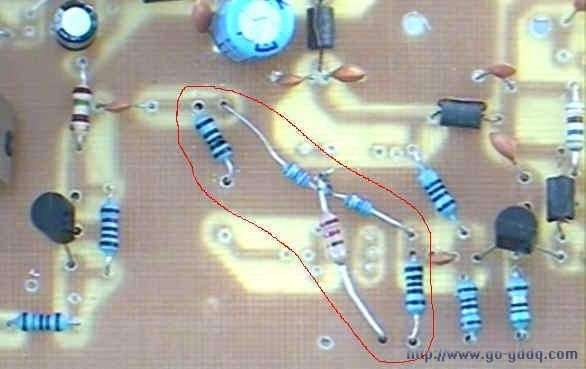
The circuit design guiding ideology can debug without any RF instrument, its performance can not be achieved the indicators of professional equipment, but its performance should be able to meet lovers experiment, audio-visual transmission effect should not be inferior to the universal machinelevel.
The transmitter is composed by two parts of the modulator and RF amplifier used in the circuit all the most common is the most classic circuit. The circuit structure of the RF circuits often do not have any particular place, the key is matching circuit parameters according to different operating frequency. Example, the figure is one of the most commonly used in common emitter amplification circuit.
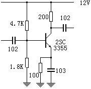
共发射极放大电路
After measurement, the circuit in a 12-channel when the gain of a dozen or so decibels, as much as 50 db below 10MHz signal amplification ability. 10MHz low frequency side, the 50 db amplifier stability work. However, when you need 12 channels of 40-50 dB of gain, certainly need three enlarged, we analyze three such amplifiers to string together what would happen.
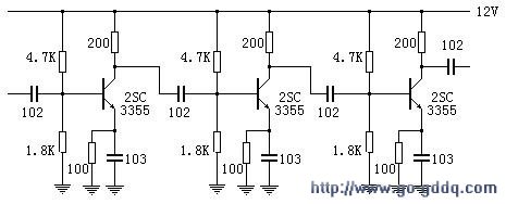
三级共发射极放大电路
Meet the requirements put on the 12 channels, a large number, but not more than 50 db. But the three amplifier put a lot of 10MHz up to more than 150 db, which is in any case can not work. One can not work the amplifier, you can obtain the required gain it? Therefore, the multi-stage RF amplifier to try to curb its lower frequency put a lot more simple method is the circuit parameters are set as shown below.
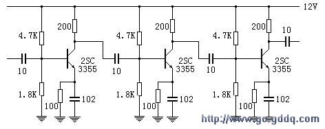
三级放大器
The one hand, the emitter capacitance decreases to reduce the gain of the single-stage low-frequency band, but the effect is smaller, and the capacitance can not be reduced too small, otherwise the amplifier circuit status will change so that you can not control. The important step is to reduce the amount of inter-stage coupling, however, reduce the interstage coupling capacitor approach although simple and effective, but at the same time to reduce the low frequency coupling, the gain of the desired band also lost a lot of this is to use the simplest way to price. The best way is to use the coupled mode frequency selection, level circuit before and after matches, but the production is difficult and not suitable for beginners selection.
Coupling between the level of this TV transmitters using the most simple way, as shown below.
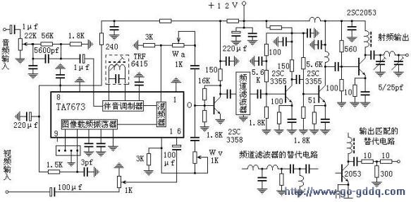
简易电视发射机1
The RF power amplifier transmitting antenna connection is amateur headache. If the antenna is a real pure resistance, of course, relatively simple, connected to the line. But the impedance of the antenna is very simple in theory, an exact match to the transmitting antenna to analyze the pure resistance, hastened to ask the transmitting antenna in the practice is equivalent to a pure resistance is difficult in amateur conditions is simply impossible. Therefore, in practice with three resistors to form a 3-dB attenuator to force the match, the effect is very good, very stable, of course, it is to consume half of the output power. In fact, half the power consumed in the 1-5 channel is also nothing to 2SC2053 in this band RF output power is not large, there are several hundred milliwatts, lost half of two hundred milliwatts, enough of. Moreover, if the matching network tone is not good, not as good as 3 db attenuator it! As for the 6-12 channel Well, matching is easier, sometimes the feeder through the septum blocking capacitor directly connected 2053 collector stable. Not work well, and then the resistor isolation is too late.
Completely installed, photographs can be the second harmonic suppression of the level of 40-50 dB below the main wave, but the overall debugging no small difficulty.
If would like to briefly pressing the Photo production, welding and correct on the arrangements for the beginner to do a few, very likely to succeed.
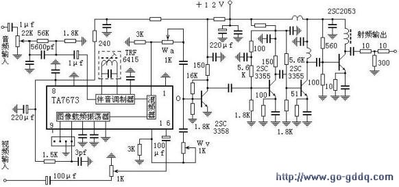
简易电视发射机2
Practice papers
Step 1: install the modulation section, the following schematic components to weld.
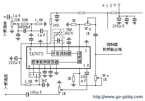 A.Measured TA7673 11 feet voltage is about 3.8V.
Two. The TV RF input (antenna port) to connect the RF modulator output, the TV should be capable of receiving RF signals, the screen displays a very pure white grating. Note: The antenna ports should be blocking function, if there is no capacitor should be connected in series to blocking.
3. Input AV signal, adjusting the adjustable device allows audio and video with excellent.
This step will determine the future audio and video quality, and adjusted to achieve satisfactory sound image to be repeated, should also be In this step, try to find the image modulation screen, the sound carrier frequency level the level of interference on the screen, accumulate the necessary experience.
Step 2: Complete the board gain stage of the welding installation, as shown below.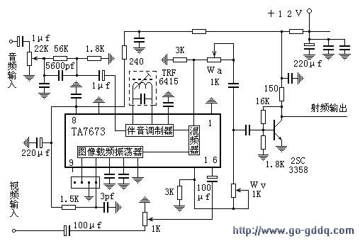 This step is relatively simple, but important, is one of the highest link of the whole gain. Usually the 2SC3355 of collector voltage in the 6-8V, the circuit will be able to work very well.
This should be a choice of good quality tubes.
The third step: This step will allow the power output stage 2SC2053 work. Its output level may reach due to the modulation level is magnified by two 100dBuV above, the small amount of some automatic gain adjustment, and input circuit dynamic range of the TV sync instability, and therefore should 2SC2053 output and the TV insert an attenuator, as shown below production.
Attenuators of Figure produced in a wide frequency range, the impedance of approximately 75 ohms.
Good attenuator board schematic below whittled.
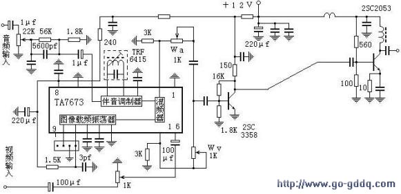
The main work of this step is to adjust the amplifier stage bias resistor so that the emitter voltage is 1V, if you understand some of the transistor circuit, usually this step will not encounter any difficulties.
According to experience, if you do the low channel, such as the 1 - channel or 2 channel, debugging this basically the end of a 2SC3358 to promote the launch tube gain enough because of the launch tube 2053 in the 1-2 channel gain high, well in 3358 nearly 40 db 30 db or so, the gain in this band is not a problem and difficult to prevent self-excited. The anti-self-excited primary means of attenuation of the signal, reduce the gain.
6-10 channels, plus a zoom, as shown below.
Plus 6-10 channel, the amplifier should be able to work in the following six channels is too gain is too high, so the resistance within the dotted line in the figure to attenuate the signal in the 3-5 channel single resistor alsocan not effectively curb the gain (and have to consider the matching factors), you will need to be connected with the attenuator, the following diagram is an example (3 channels).

简易电视发射机原理图
