FMUSER Wirless Transmit Video And Audio More Easier !
es.fmuser.org
it.fmuser.org
fr.fmuser.org
de.fmuser.org
af.fmuser.org ->Afrikaans
sq.fmuser.org ->Albanian
ar.fmuser.org ->Arabic
hy.fmuser.org ->Armenian
az.fmuser.org ->Azerbaijani
eu.fmuser.org ->Basque
be.fmuser.org ->Belarusian
bg.fmuser.org ->Bulgarian
ca.fmuser.org ->Catalan
zh-CN.fmuser.org ->Chinese (Simplified)
zh-TW.fmuser.org ->Chinese (Traditional)
hr.fmuser.org ->Croatian
cs.fmuser.org ->Czech
da.fmuser.org ->Danish
nl.fmuser.org ->Dutch
et.fmuser.org ->Estonian
tl.fmuser.org ->Filipino
fi.fmuser.org ->Finnish
fr.fmuser.org ->French
gl.fmuser.org ->Galician
ka.fmuser.org ->Georgian
de.fmuser.org ->German
el.fmuser.org ->Greek
ht.fmuser.org ->Haitian Creole
iw.fmuser.org ->Hebrew
hi.fmuser.org ->Hindi
hu.fmuser.org ->Hungarian
is.fmuser.org ->Icelandic
id.fmuser.org ->Indonesian
ga.fmuser.org ->Irish
it.fmuser.org ->Italian
ja.fmuser.org ->Japanese
ko.fmuser.org ->Korean
lv.fmuser.org ->Latvian
lt.fmuser.org ->Lithuanian
mk.fmuser.org ->Macedonian
ms.fmuser.org ->Malay
mt.fmuser.org ->Maltese
no.fmuser.org ->Norwegian
fa.fmuser.org ->Persian
pl.fmuser.org ->Polish
pt.fmuser.org ->Portuguese
ro.fmuser.org ->Romanian
ru.fmuser.org ->Russian
sr.fmuser.org ->Serbian
sk.fmuser.org ->Slovak
sl.fmuser.org ->Slovenian
es.fmuser.org ->Spanish
sw.fmuser.org ->Swahili
sv.fmuser.org ->Swedish
th.fmuser.org ->Thai
tr.fmuser.org ->Turkish
uk.fmuser.org ->Ukrainian
ur.fmuser.org ->Urdu
vi.fmuser.org ->Vietnamese
cy.fmuser.org ->Welsh
yi.fmuser.org ->Yiddish
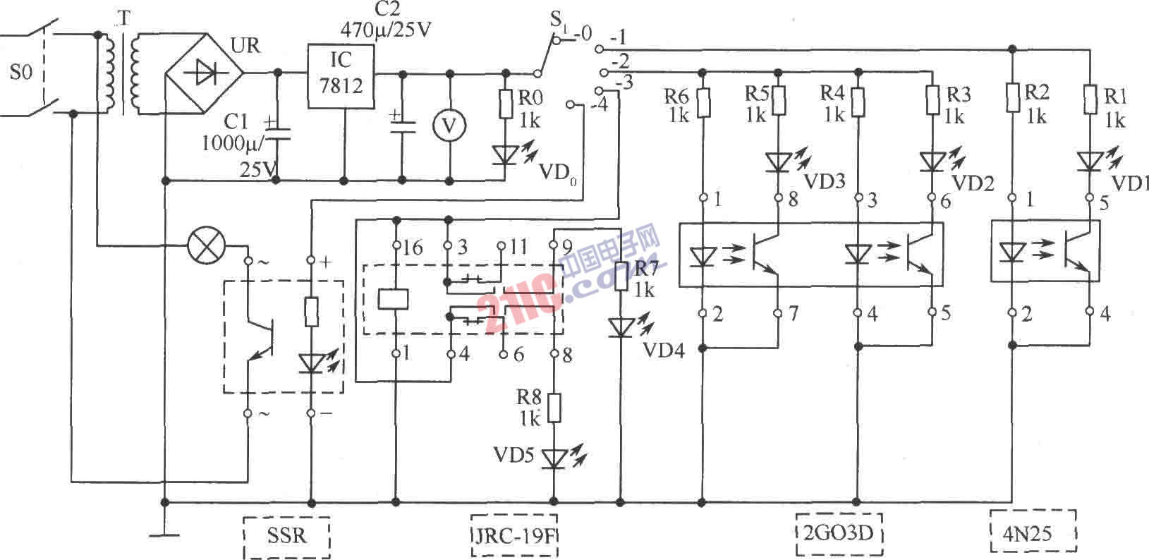
Figure shows the FM transmitter function detector circuit. AC 220V mains power switch S0 added by the power transformer T, the output voltage 15V AC, then by UR bridge rectifier, C1 filter, and then the +12 V regulator IC IC output voltage, 12V DC voltage meter reading instruction, VD0 as a power indicator, R0 is the current limiting resistor. R1 ~ R8 and role in resistance and R0 are the same. +12 V power select switch S1, on receiving the measurement, usually the switch to the empty leg. If the measurement is the optocoupler 4N25, this component a total of 6 feet, 1 foot and 2 feet inputs (1 pin is connected, 2 foot ground), 4 feet and 5 feet output (4 pin to ground, 5 feet then high potential). To plug into the appropriate tube seat, pay attention to the corresponding pin and the tube socket (Mark the best seat in the tube), or components will be burned, and then measuring switch S1 to the S1-1 on the spin, and then open the power switch S0, then light-emitting diode VD1 is not lit, indicating 4N25 damaged (open circuit or short circuit). If VD1 light, indicating optocoupler 4N25 is good, then select the test finished back S1.0 S1-1 switch positions. Similarly, S1-2 block is a measure of optocoupler 2G03D, this coupler is coupled conduction of two devices, a pin (positive) and 2 feet (to) is the input side, corresponding to 8 feet (high potential) and 7 feet (to) is the output; 3 feet (positive) and 4 feet (to) is another input, 6 feet (high potential) and 5 feet (to) is the output. Plug in the measured components, if the VD2 and VD3 are bright, indicating 2G03D good; if VD2 and VD3 two do not have a light or not light, indicating components damaged or partially damaged, it must be replaced. Select switch S1-3 block is a measure of small electromagnetic relay JRC-19F/012M's. 1 foot and 16-pin +12 V line of pack voltage is connected, 3 feet and 9 feet, 4 feet and 8 feet for the two groups of normally open contacts. When measuring this device, the first plug JRC-19F, the rotary selector switch to the S1-3 position, turn the power switch S0. If the VD4 and VD5 are bright, indicating the relay pull-normal: If a LED is not lit, indicating the corresponding no pull on the contacts; if the two lights off, and that two groups of bad contacts or line of pull package damage. Select switch S1-4 block is a measure of solid-state relay SSR devices. +12 V power input termination, output termination AC 220V control circuit, where light bulbs replaced with low-power, solid state relay will insert the appropriate self-control Block (you must not plug the wrong location), the rotary switch to S1.4, the Turn on the power switch S0, 220V light bulb lit, it shows normal SSR work, otherwise this component is damaged.
Our other product:
Professional FM Radio Station Equipment Package
|
||
|
Enter email to get a surprise
es.fmuser.org
it.fmuser.org
fr.fmuser.org
de.fmuser.org
af.fmuser.org ->Afrikaans
sq.fmuser.org ->Albanian
ar.fmuser.org ->Arabic
hy.fmuser.org ->Armenian
az.fmuser.org ->Azerbaijani
eu.fmuser.org ->Basque
be.fmuser.org ->Belarusian
bg.fmuser.org ->Bulgarian
ca.fmuser.org ->Catalan
zh-CN.fmuser.org ->Chinese (Simplified)
zh-TW.fmuser.org ->Chinese (Traditional)
hr.fmuser.org ->Croatian
cs.fmuser.org ->Czech
da.fmuser.org ->Danish
nl.fmuser.org ->Dutch
et.fmuser.org ->Estonian
tl.fmuser.org ->Filipino
fi.fmuser.org ->Finnish
fr.fmuser.org ->French
gl.fmuser.org ->Galician
ka.fmuser.org ->Georgian
de.fmuser.org ->German
el.fmuser.org ->Greek
ht.fmuser.org ->Haitian Creole
iw.fmuser.org ->Hebrew
hi.fmuser.org ->Hindi
hu.fmuser.org ->Hungarian
is.fmuser.org ->Icelandic
id.fmuser.org ->Indonesian
ga.fmuser.org ->Irish
it.fmuser.org ->Italian
ja.fmuser.org ->Japanese
ko.fmuser.org ->Korean
lv.fmuser.org ->Latvian
lt.fmuser.org ->Lithuanian
mk.fmuser.org ->Macedonian
ms.fmuser.org ->Malay
mt.fmuser.org ->Maltese
no.fmuser.org ->Norwegian
fa.fmuser.org ->Persian
pl.fmuser.org ->Polish
pt.fmuser.org ->Portuguese
ro.fmuser.org ->Romanian
ru.fmuser.org ->Russian
sr.fmuser.org ->Serbian
sk.fmuser.org ->Slovak
sl.fmuser.org ->Slovenian
es.fmuser.org ->Spanish
sw.fmuser.org ->Swahili
sv.fmuser.org ->Swedish
th.fmuser.org ->Thai
tr.fmuser.org ->Turkish
uk.fmuser.org ->Ukrainian
ur.fmuser.org ->Urdu
vi.fmuser.org ->Vietnamese
cy.fmuser.org ->Welsh
yi.fmuser.org ->Yiddish
FMUSER Wirless Transmit Video And Audio More Easier !
Contact
Address:
No.305 Room HuiLan Building No.273 Huanpu Road Guangzhou China 510620
Categories
Newsletter