
There is no thrill like the thrill you get from operating equipment you have built yourself. If you have never built a project from a magazine before, let this be your first--you'll see how much satisfaction and fun you can have!
The FM transmitter is designed run from a 9-volt battery and is made from readily available parts. The author's primary use is as a baby monitor, but uses of a transmitter like this one are almost limitless. It is very sensitive, and easily capable of picking up a conversation in any part of the room. The dimensions and values give here will allow static-free reception within the perimeter of most homes.
No license is required for this transmitter according to FCC regulations regarding wireless microphones. (The emissions must stay within a band of 200 KHz, its output between 88 and 108 MHz, and the field strength of the radiated emissions must not exceed 50uV/m at a distance of 15 meters (45 feet) from the device.)
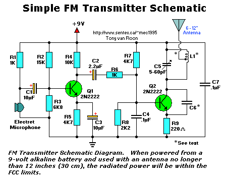
If powered from a 9-volt battery and used with an antenna no longer than 12 inches, the transmitter's radiated power will be within the FCC limits. The FCC takes a dim view of persons operating outside the legal power limits, so please do not substitute any components in this circuit which would alter the output power.
Parts List:
All resistors are 1/8-watt, 5%.

R1,R6 = 1K             C1,C3 = 10uF/25V, electrolytic
   R2 = 15K               C2 = 2.2uF/25V, electrolytic
   R3 = 6K8            C4,C7 = 0.1uF/25V, ceramic
   R4 = 10K               C5 = 5 to 60pF, trimmer
R5,R7 = 4K7               C6 = hand-made (see text)
   R8 = 2K2            Q1,Q2 = 2N2222(A), NPN transistor
   R9 = 220 ohms          L1 = hand-made (see text)

Miscellaneous: perforated construction board, 9-Volt battery, battery clip,
               electret microphone, 24-gauge insulated wire, bare wire, solder.
Circuitry:
Take a look at the schematic above. Audio is picked up from the room by an electret microphone and amplified by Q1. Resistors R2-R5 set up the DC operating bias of Q1. Capacitor C3 serves to improve the AC response to the audio voltage, and C2 blocks the DC bias and couples the AC to the next stage, where the RF action takes place. The amplified AC voltage from Q1 is routed to the base of Q2. Transistor Q2 and associated circuitry (C5 and the inductor) form an oscillator that operates in the 80-130 MHz range, which is your regular dial on any FM radio.
The oscillator is voltage-controlled, so it is modulated by the audio voltage that is applied to the base of Q2. Resistor R6 limits the input to the RF section, and its value can be adjusted as necessary to limit the volume of the input. That will help control the amount of distortion you have on very loud inputs.
Resistors R7-R9 set the DC operating bias of Q2, another 2N2222 that's used as the oscillator and modulator of the transmitter. Capacitor C5 is a 6-50pF trimmer capacitor that's used to tune the oscillator tank circuit, and C4 routes the RF from the oscillator to ground to prevent unstable operation.
 Construction:
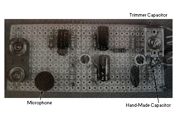
The FM transmitter is built on a piece of perforated construction board (a.k.a. 'perf-board') with 0.1-inch hole spacing. Component spacing is not critical, but placement is. You should place the components on the board in a layout that is similar to the prototype shown. Generally, you will also want to make the transmitter as small as possible.
Let's start from the left side of the schematic and work o the tright. You'll want to cut out a piece of perfboard that is 12 holes wide and 30 holes long. That will give you plenty of room to work with, but still produce a small unit. First lay out two power lines on the board with bare wire; the positive supply from the battery will be on top, and the negative (ground) will be on the bottom.
A 1K resistor (R1) supplies the bias voltage for the microphone. Remember to install the resistor vertically, next to the positive supply line, and bend the other end of the lead to the board. Go through the board and down toward the ground bus. Now insert the micophone leads into the board, making sure that the ground lead of the microphone can be soldered to the ground bus on the board. Route the lead from R1 to the positive lead of the microphone and solder it. The 10-uF capacitor, C1, should be placed in the middle of the board, oriented as shown on the schematic, and soldered to the microphone/R1 junction.
This project requires two hand-made parts--coil L1 and capacitor C6--but you make both of them yourself using only wire and a common pencil for the coil form. The inductor ismade by winding two pieces of 24-gauge insulated wire, laid side-by-side, around the pencil six times. Remove the coil you have formed and unscrew the two coils apart from each other. One of these coils, the better-looking of the two, will be used in the tank circuit (L1) and the other can be used in the next one you build.
The other hand-made component, capacitor C6, is part of the oscillator feedback. To make this small value capacitor, take a 4-inch piece of 24-gauge insulated wire, bend it over double and, beginning 1/2-inch from the open end, twist the wire as if you were forming a rope. When you have about 1 inch of twisted wire, stop and cut the looped end off leaving about 1/2-inch of twisted wire (this forms the capacitor) and 1/2-inch of untwisted wire for leads.
Capacitor C7, a 0.1uF capacitor, is one of the most critical components in the circuit. You must place it across the L1-Q2-R9 assembly, as shown in Fig. 1, to reduce the amout of RF feedback you'll get iinto the rest of the circuit. The antenna (more 24-gauge wire) shoucl be soldered to the coil you made, about 2-turns up from the bottom, or the transistor side, and should be about 8-12-inches long.
Operation:
To use the transmitter, set up a radio in the area at least 10 feet (3 meters) from the project. Find a blank spot on the FM dial and turn the radio up so you can hear the static.
Connect a 9-volt battery to the transmitter and listed to the radio. Slowly adjust the tank capacitor (C5) until you "quiet" the receiver; this is the tuned spot. Note that when you move your hand from the transmitter, you will detune the circuit somewhat. It is usually best to leave it detuned and tune the radio in to get the best reception. If you et the tuning randge you desire, you can squeeze the coils in the tank circuit closer together to raise the frequency, or pull them apart just a little to lower it.
The circuit works best when powered by a battery, but if a wall adapter is required, make certain that the ripple voltage is as low as possible, or you will get hum in the receiver. R-E
Our other product:


 Construction:


