WLAN antenna 2.4 GHz Do-It-Yourself
Homebrew outdoor antenna to 2.4 GHz band.
Antenna gain is comparable to panel antennas including the Freedom Antenna Set sold in Finland. Comparing is made simple by connecting antennas to same computer with Orinoco WLAN card and indicating results in Link Test of the Client Manager. My antenna has been found about 2 dB better gain than the Freedom antenna, which is specified as 12 dBi antenna. And prices ... Oh, I need not even mention this! In Europe there is a maximum allowable output power of 20 dBm (100 mW) because of the ETSI standard we use. While Orinoco "red" card is transmitting 8 dBm signal and my antenna gain is about 14 dBi there has to be only 2 dB cable and connector loss to keep output level below 20 dBm. The Orinoco Adapter Cable takes about 1 dB and H1000 antenna cable takes 2 dB/10m. So using 5 metres antenna cable there is no risk of exceeding the output power within the ETSI standard. This antenna can also be built without the Ring to decrease antenna gain if needed especially with very short antenna cable.
Dimensioning
The very first point in antenna dimensioning is to calculate the wavelength (the Lambda character has been replaced with letter L ):
L /mm = 300 / (f/GHz) -> at 2.45 GHz L = 122 mm.
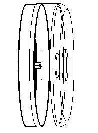
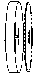
Antenna picture without mast fasteners:
With the cover Without the cover
 Main parts can been found even in mama's dish cabinet but maybe safer to buy them from a department store. The Reflector is made from an aluminium cake pan and the Cover from a plastic microwave bulb, both 240--250 mm dia. The pan must be straight and smooth without profilations and the sides will be orthogonal with the bottom. If you find a pan made from stainless steel may be that may be better. I used a pan from italo ottinetti code 140024 , whose sides were 60 mm and I cut them to 32 mm.
Other parts needed:
A piece of copper water conduit, internal dia 10 mm, length below 40 mm
A piece of brass rod, outer dia 4-4.5 mm, length < 40 mm
Copper wire about 2 mm dia, length < 70 mm
N-connector, panel socket
A couple pieces of tinned steel sheet e.g. from tin can
A piece of PVC coated electric wire 1,5 mm2
Screws and bolts M3, solder tin etc.
Antenna construction:
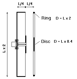 The Reflector (aluminium pan) dia = L x 2, the height of the sides = L/4.
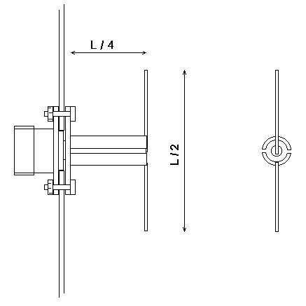
In the centre of the bottom there is the N connector to left and the dipole to right. A distance from bottom to the dipole is little more than L/4. The Dipole is mounted with an air-insulated coaxial type foot, whose impedance is 50 ohm and length L/4. Inner wire of the coaxial is made of 4 to 4.5 mm rod or conduit and shield made from split copper conduit which internal dia is 10 mm. To the right of the dipole there is a disc whose dia is L x 0.4 (= 49 mm) and distance from the dipole is again L/4. Disc material can be thin aluminium or tinned steel sheet.
At same distance as the disc, there is also a ring made from pvc-coated electric wire 1,5 mm2 by binding it to ring diameter about L x 2. It is not neccessary to short the ends of the ring, I left ~ 1 mm space. If you want you can short the ends together as well. PVC coating on the wire has no magic, you can use e.g 2 mm clear copper wire as well.
I mounted the Disc and the Ring to the plastic cover made from microwave oven bulb. A piece of plastic sheet and glue are needed to mount the disk. The ring I glued inside the cover, so the diameter of the ring becomes somewhat smaller than L/4.
Assembling:
 The sides of the reflector (cake pan) must be L/4 or 32 mm, so extra height must be cut away. In the centre of the pan there will be a hole 12 dia and four 3.5 mm holes according the N-connector. The feet of the dipole is made of split copper conduit and inside it a rod or a pipe. The impedance of the feet must be 50 ohm which actually means the ratio of inner dia of the outer conduit and dia of the inner rod be 2.3. It is quite near when inner rod or pipe has 4 to 4.5 mm outer dia and copper conduit has 10 mm inner dia. The exact equation of Impedance versus Diameter ratio is:
Z = 138 * Log(D/d)
The table of Impedance and Diameter Ratio
D = inner diameter of the tube
d = outer dia of the rod Z = impedance in free air
| D / d |
Z / Ohm |
| 2.2 |
47.3 |
| 2.3 |
50 |
| 2.4 |
52.5 |
| 2.5 |
54.9 |
If the inner wire is made from rod it is good idea to drill axially a 3 mm hole on the end of it so the rod can be solder firmly to the inner tap of the N connector. The length of the rod becomes about L/4, but it is better first to leave it longer and cut it later after the parts are first pre-assembled.
The copper conduit must be split with a metal saw as accurately as possible and deburred with a file. The end of the split conduit is then fastened to the centre of the pan. It is not possible to solder it directly to aluminium but we made a flange from tinned steel sheet to same dimensions as the flange of the N connector. In the middle of the flange is drilled a hole equal the outer dia of the conduit and four 3.5 mm holes as in the N connector. The one end of the split conduit is then soldered in the centre hole of the flange while keeping the width of the slots between halves to 1-1.5 mm.
The split conduit is then cut so that the length of the open slots becomes a very accurate L/4. This is the most accurate point in the antenna construction. Among with many roles, the slot acts as a band pass filter which rejects other frequencies than nominal HF.
Now is good time to pre-assemble parts. With four 3 mm screws, the N connector with the centre rod and the flange with split conduit are assembled on opposite sides of the centre hole of the pan, N connector to the outer side. The centre rod is now cut to same length as the split conduit.
The Dipole was made from 2 mm enamelled wire. The one arm of the dipole is soldered both to the centre rod and to the half of the copper conduit. The second arm of the dipole is soldered only to the second half of the conduit. The arms of the dipole are cut to L/4 from axle, so total width of the dipole becomes L/2.
Before soldering it is good idea to file grooves for dipole wire to the centre rod and the halves of the conduit.
To the right of the dipole there is the disc and the wire ring which can be assembled to the cover bulb so that their distance from dipole becomes to L/4.
The cover bulb can be locked with three 3 mm screws and sealed with silicone mass as well as the N connector joint.
On the very lowest point of the pan there must be drilled a small hole for condensed water exhaust.
Frequently asked details
|
|
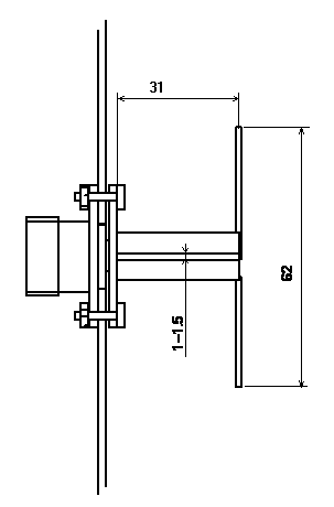
The most important dimension of the antenna is the length of the slot,
which must be 31 mm @2.45 GHz.
I don't know the optimum width of the slot. I made it with metal handsaw inserting two blades parallel. So it becomes ca. 1.5 mm.
|
Yes really!
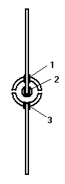
The one arm of the dipole is soldered both to the centre rod (2) and to the half of the copper conduit (1). The second arm of the dipole is soldered only to the second half of the conduit (3).
It doesn't mean a "short circuit". Remember the signal here is not direct current but high frequency !
See: Special Cases of Quarter Wavelength
|
Mast mounting of the antenna
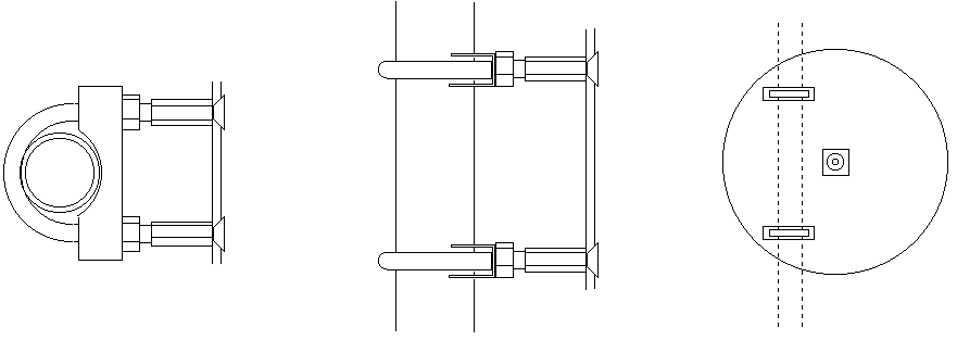
Mast fasteners can be made from exhaust pipe clamps. See above some mounting ideas. Be careful not to mount clamps in the centre line otherwise the mast prevents connection of cable to the N connector. The rightmost picture is from back side.
Lightning protection
When the antenna is mounted above the roof there becomes a risk of lightning damage to the WLAN card.
The mast has to be grounded firmly e.g with 16 mm2 copper rope to a good earthing point. Lightning protection module is recommended between antenna cable at the place where the cable enters the roof.
Antenna cable and connectors
Cable type Belden H1000 is found to be low loss on microwave band and it is not very expensive. All cable and connector impedances must be 50 ohm. Outdoor connections are not watertight enough as such. So called self vulcanizing tape is best choice to wind over connection and above all there have to be wound black electrical tape to protect the vulcanizing tape against ultraviolet light. See cabling details .
Sources
Antenna construction is from page http://6mt.com/2304tech.htm where is found an item MICROWAVE ANTENNA YOU CAN BUILD (73 10-82) c56.zip . I have dimensioned it to 2.4 GHz band and made some additions.
Our other product:


