Radio remote control is used in many fields due to its advantages such as long transmission distance, strong anti-interference ability, and non-directionality. However, due to the complexity of electrical appliances, huge transmission equipment, and difficulty in debugging, it has always been restricted in the civilian field. With the development of electronic technology, these problems have been solved and made it have strong vitality.
Early transmitters used LC oscillators more, and the frequency drift was more serious. The emergence of SAW devices has solved this problem. Its frequency stability is roughly the same as that of crystal oscillators, and its fundamental frequency can reach several hundred megahertz or even gigahertz. No frequency multiplication is required, and the circuit is extremely simple compared to crystal oscillators. The following two circuits are common transmitter circuits. Due to the use of SAW devices, the circuit works very stably. Even if the antenna, SAW or other parts of the circuit are grasped by hand, the transmitting frequency will not drift. Compared with Figure 1, Figure 2 has a higher transmit power. Can reach more than 200 meters.
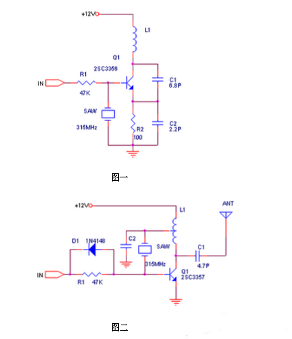
The picture above shows a common transmitter circuit
Although the performance of OOK modulation is poor, its circuit is simple and easy to implement, and its work is stable, so it has been widely used. It is almost invariably used in automobile and motorcycle alarms, warehouse gates, and home security systems. Circuit.
Wireless receiving circuit design
The receiver can use super regenerative circuit or super heterodyne circuit. The cost of super regenerative circuit is low, and the power consumption can reach about 100uA. The superheterodyne receiver in the middle stage is similar. However, the super-regenerative circuit has poor working stability and poor selectivity, which reduces the anti-interference ability. The figure below shows a typical super-regenerative receiving circuit.
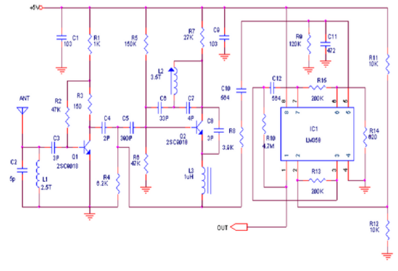
Wireless receiving circuit
The sensitivity and selectivity of the superheterodyne circuit can be done very well. The single-chip integrated circuit introduced by Micrel of the United States can complete the reception and demodulation. Its MICRF002 is an improved type of MICRF001. Compared with MICRF001, it has lower power consumption. And has a power shutdown control terminal. MICRF002 has stable performance and is very simple to use. Compared with the ultra-reproduction circuit, the disadvantage is the high cost (RMB35). The following is its pin arrangement and recommended circuit.
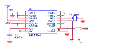
ICRF002 uses a ceramic resonator instead of a different resonator, and the receiving frequency can cover 300-440MHz.
MICRF002 has two working modes: scanning mode and fixed mode. The scanning mode accepts bandwidth up to several hundred KHz. This mode is mainly used with LC oscillating transmitters because the frequency drift of LC transmitters is large. In scanning mode, the data communication rate is 2.5KBytes per second. The bandwidth of the fixed mode is only tens of KHz. This mode is used for matching transmitters that use crystal oscillator to stabilize the frequency. The data rate can reach 10KBytes per second. Working mode selection is realized through the 16th pin (SWEN) of MICRF002. In addition, use the wake-up function to wake up the decoder or CPU to minimize power consumption.
MICRF002 is a complete single-chip superheterodyne receiving circuit, which basically realizes "direct output of data" after "antenna input", and the receiving distance is generally 200 meters.
Wireless transmitting circuit based on T630 radio remote control transmitting and receiving head Wireless receiving circuit
Here to introduce a method of making radio remote control transmitter and receiver (T630/T631).
Circuit Introduction
The radio remote control transmitter T630 is a miniature transmitter with a built-in wire without signal. Its transmission frequency is 265MHz. When powered by a 12V power supply, the remote control distance is 100M, the working current is only 4mA, and its volume is 28X12X10mm. The radio receiver T631, a built-in antenna, is a receiver and demodulator like a TV tuner. Its typical working voltage is 6V, standby working current is 1mA, receiving frequency is 265MHz, and its volume is only 31X23X10mm. They can be used to easily produce various radio remote control devices, which have the advantages of miniaturization, long transmission distance, low power consumption, and strong anti-interference ability. It can easily replace infrared, ultrasonic transmitter and receiver.
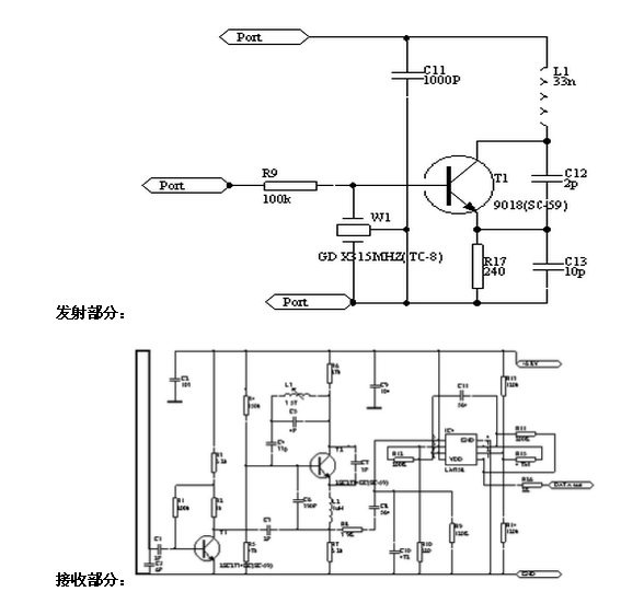
The circuit principle of radio transmitter T630 is shown in the figure. Circuit four transmitting tube V1 and peripheral components C1, C2, L1, L2, etc. constitute an ultra-high frequency transmitting circuit with a frequency of 265MHz, which is launched into the air through the loop antenna L2. Antenna L2 uses silver-plated wire or enameled wire with a diameter of 1.5mm, and the antenna size is 24mm (length) X 9mm (height). The triode V1 selects the high-frequency launch tube BE414 or 2SC3355.
The circuit principle of the radio remote control receiver T631 is shown in the figure. The receiving circuit is mainly composed of V1, IC, etc. V1 and C7, C9, L2 and other components form an ultra-high frequency receiving circuit. Fine-tune C9 to change its receiving frequency and make it strictly aligned with the 265MHz transmitting frequency. When the antenna L2 receives the modulated wave, it is tuned by V1 to amplify the low-frequency component, and then pre-amplified by V2 and then sent to the IC LM358. After further amplification and shaping, it is output by the 7th pin of the LM358. The actual size of the printed circuit board is 31mmX23CC. The size is 27mm (length) X9mm (height). OUT is the signal output terminal, and the transistor V1 selects BE415 or 2SC3355. The capacitor C9 can be a small adjustable capacitor. IC selects LM358 for use.
In order to reduce the volume in the transmitting and receiving circuits, all resistors are made of 1/8W or 1/16W metal film resistors; electrolytic capacitors are also ultra-small capacitors, and other capacitors are all high-frequency ceramic capacitors. When soldering, the component pins should be cut as short as possible to make it close to the circuit board. The circuit board material should be a high-frequency circuit board.
The following are two-carrier transceivers that use surface acoustics. Compared with the circuits introduced above, they have a longer transmission distance, stronger anti-interference ability, and easier production and debugging.
Our other product:


