What is the Voltage Standing Wave Ratio? How to calculate VSWR?
"VSWR (Voltage Standing Wave Ratio), is a measure of how efficiently radio-frequency power is transmitted from a power source, through a transmission line, into a load (for example, from a power amplifier through a transmission line, to an antenna)." This is the concept of VSWR. More about VSWR, such as the influencing factors of VSWR, the impact on the transmission system, the difference with SWR, etc. This article can give you a detailed explanation.
According to Wikipedia, standing wave ratio (SWR) defined as:
"a measure of impedance matching of loads to the characteristic impedance of a transmission line or waveguide. Impedance mismatches result in standing waves along the transmission line, and SWR is defined as the ratio of the partial standing wave's amplitude at an antinode (maximum) to the amplitude at a node (minimum) along the line."
SWR is usually measured using a dedicated instrument called an SWR meter. Since SWR is a measure of the load impedance relative to the characteristic impedance of the transmission line in use (which together determine the reflection coefficient as described below), a given SWR meter can interpret the impedance it sees in terms of SWR only if it has been designed for that particular characteristic impedance. In practice most transmission lines used in these applications are coaxial cable with an impedance of either 50 or 75 ohms, so most SWR meters correspond to one of these.
Checking the SWR is a standard procedure in a radio station. Although the same information could be obtained by measuring the load's impedance with an impedance analyzer (or "impedance bridge"), the SWR meter is simpler and more robust for this purpose. By measuring the magnitude of the impedance mismatch at the transmitter output it reveals problems due to either the antenna or the transmission line.
By the way, if you think you have never experienced a standing wave personally, it's very unlikely. Standing waves in a microwave oven are the reason that food is cooked unevenly (the turntable is a partial solution to that problem). The wavelength of the 2.45 GHz signal is about 12 centimeters, or about five inches. Nulls in the radiation (and heating) will be separated at a distance similar to wavelength.
The reflection coefficient is a parameter that describes how much of an electromagnetic wave is reflected by an impedance discontinuity in the transmission medium, equaling to the ratio of the amplitude of the reflected wave to the incident wave. The reflection coefficient is a very useful quality when determining VSWR or investigating the match between, for example, a feeder and a load. The Greek letter Γ is typically used for reflection coefficient, although σ is also often seen.
Reflection Coefficient
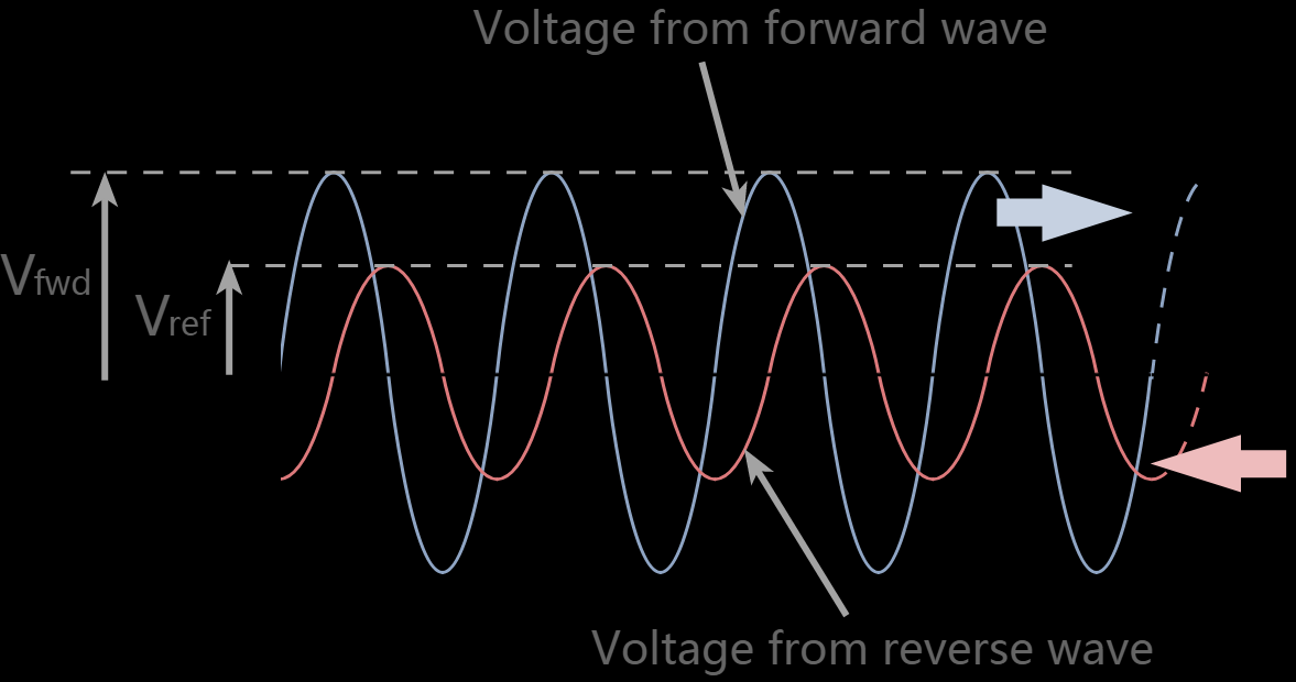
Using the basic definition of the reflection coefficient, it can be calculated from a knowledge of the incident and reflected voltages.
Where:
Γ = reflection coefficient
Vref = reflected voltage
Vfwd = forward voltage
2) Return Loss & Resertion Loss
Return loss is the loss of signal power due to signal reflection or return by a discontinuity in a fiber-optic link or transmission line, and its unit of expression is also in decibels (dBs). This impedance mismatch can be with a device inserted in the line or with the terminating load. Moreover, return loss is the relationship between both the reflection coefficient (Γ) and the standing wave ratio (SWR), and is always a positive number, and a high return loss is a favorable measurement parameter, and it typically correlates to a low insertion loss. Incidentally, if you increase the return loss, it will correlate to a lower SWR.
The loss of signal, which occurs along the length of a fiber optic link, is called insertion loss. Insertion loss is, however, a natural occurrence that occurs with all types of transmissions, whether it is data or electrical. Furthermore, as it is with basically all physical transmission lines or conductive paths, the longer the path, the higher the loss. Moreover, these losses also occur at each connection point along the line, including splices and connectors. This particular measurement parameter is expressed in decibels and should always be a positive number. However, should, does not mean always, and if by chance, it is negative, that is not a favorable measurement parameter. In some instances, an insertion loss may appear as a negative parameter measurement.
Return Loss & Insertion Loss
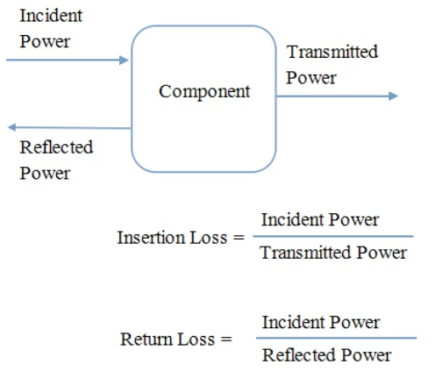
So now, let us examine the above diagram in detail so that we may gain a better understanding of how insertion loss and return loss interact. As you can see, incident power travels down a transmission line from the left until it reaches the component. Once it reaches the component, a portion of the signal is reflected back down the transmission line towards the source from which it came. Also, keep in mind that this portion of the signal does not enter the component.
The remainder of the signal does indeed enter the component. There some of it gets absorbed, and the rest passes through the component into the transmission line on the other side. The power that comes out of the component is called the transmitted power, and it is less than the incident power for two reasons:
① A portion of the signal gets reflected.
② The component absorbs a portion of the signal.
So, in summary, we express insertion loss in decibels, and it is the ratio of incident power to transmitted power. Furthermore, we can summarize that return loss, which we also express in decibels is the ratio of incident power to reflected power. Therefore, we can see how the two types of loss measurement parameters help to accurately gauge the overall efficiency of a measurable signal and component within a system or in a through path.
In today’s electronics practices, in terms of use, return loss is preferable to SWR since it affords better resolution for smaller values of reflected waves.
3) What is Impedence Matching
Impedance matching is designing source and load impedances to minimize signal reflection or maximize power transfer. In DC circuits, the source and load should be equal. In AC circuits, the source should either equal the load or the complex conjugate of the load, depending on the goal. Impedance (Z) is a measure of the opposition to electrical flow, which is a complex value with the real part being defined as the resistance (R), and the imaginary part is called the reactance (X). The equation for impedance is then by definition Z=R+jX, where j is the imaginary unit. In DC systems, the reactance is zero, so the impedance is the same as the resistance.
The Voltage Standing Wave Ratio (VSWR) is an indication of the amount of mismatch between an antenna and the feed line connecting to it. (Click here to pick our antennna products) This is also known as the Standing Wave Ratio (SWR). The range of values for VSWR is from 1 to ∞ . A VSWR value under 2 is considered suitable for most antenna applications. The antenna can be described as having a “Good Match”. So when someone says that the antenna is poorly matched, very often it means that the VSWR value exceeds 2 for a frequency of interest. Return loss is another specification of interest and is covered in more detail in the Antenna Theory section. A commonly required conversion is between return loss and VSWR, and some values are tabulated in chart, along with a graph of these values for quick reference.
Let's take a quick view video about VSWR!
2) Factors Affects VSWR
· Frequency
· Antenna ground
· Nearby metal objects
· Type of antenna construction
· Temperature
3) SWR vs VSWR vs ISWR vs PSWR
SWR is a concept, i.e. the standing wave ratio. VSWR is actually how you make the measurement, by measuring the voltages to determine the SWR. You can also measure the SWR by measuring the currents or even the power (ISWR and PSWR). But for most intents and purposes, when someone says SWR they mean VSWR, in common conversation they are interchangeable.
· SWR: SWR stands for standing wave ratio. It describes the voltage and current standing waves that appear on the line. It is a generic description for both current and voltage standing waves. It is often used in association with meters used to detect the standing wave ratio. Both current and voltage rise and fall by the same proportion for a given mismatch. · VSWR: The VSWR or voltage standing wave ratio applies specifically to the voltage standing waves that are set up on a feeder or transmission line. As it is easier to detect the voltage standing waves, and in many instances voltages are more important in terms of device breakdown, the term VSWR is often used, especially within RF design areas.
For most practical purposes, ISWR is the same as VSWR. Under ideal conditions, the RF voltage on a signal transmission line is the same at all points on the line, neglecting power losses caused by electrical resistance in the line wires and imperfections in the dielectric material separating the line conductors. The ideal VSWR is therefore 1:1. (Often the SWR value is written simply in terms of the first number, or numerator, of the ratio because the second number, or denominator, is always 1.) When the VSWR is 1, the ISWR is also 1. This optimum condition can exist only when the load (such as an antenna or a wireless receiver), into which RF power is delivered, has an impedance identical to the impedance of the transmission line. This means that the load resistance must be the same as the characteristic impedance of the transmission line, and the load must contain no reactance (that is, the load must be free of inductance or capacitance). In any other situation, the voltage and current fluctuate at various points along the line, and the SWR is not 1.
4. How VSWR Affects Performance In The Transmission System
There are many ways in which VSWR affects the performance of a transmission system or any system that may use radio frequencies and identical impedances. Although VSWR is used normally, both voltage and current waves can cause problems.
· Transmitter power amplifiers can be damaged: The increased levels of voltage and current seen on the feeder as a result of the standing waves, can damage the output transistors of the transmitter. Semiconductor devices are very reliable if operated within their specified limits, but the voltage and current standing waves on the feeder can cause catastrophic damage if they cause the devise to operate outside their limits.
· PA Protection reduces output power: In view of the very real danger of high SWR levels causing damage to the power amplifier, many transmitters incorporate protection circuitry which reduces the output from the transmitter as the SWR rises. This means that a poor match between the feeder and antenna will result in a high SWR which causes the output to be reduced and hence a significant loss in transmitted power.
· High voltage and current levels can damage feeder: It is possible that the high voltage and current levels caused by the high standing wave ratio can cause damage to a feeder. Although in most cases feeders will be operated well within their limits and the doubling of voltage and current should be able to be accommodated, there are some circumstances when damage can be caused. The current maxima can cause excessive local heating which could distort or melt the plastics used, and the high voltages have been known to cause arcing in some circumstances.
· Delays caused by reflections can cause distortion: When a signal is reflected by mismatch, it is reflected back towards the source, and can then be reflected back again towards the antenna. A delay is introduced equal to twice the transmission time of the signal along the feeder. If data is being transmitted this can cause inter-symbol interference, and in another example where analogue television was being transmitted, a “ghost” image was seen.
· Reduction in signal compared to perfectly match system: Interestingly the loss in signal level caused by a poor VSWR is not nearly as great as some may imagine. Any signal reflected by the load, is reflected back to the transmitter and as matching at the transmitter can enable the signal to be reflected back to the antenna again, the losses incurred are fundamentally those introduced by the feeder. As a guide a 30 metre length of RG213 coax with a loss of around 1.5 dB at 30 MHz will mean that an antenna operating with a VSWR will only give a loss of just over 1dB at this frequency compared to a perfectly matched antenna.
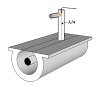
Many different methods can be used to measure standing wave ratio. The most intuitive method uses a slotted line which is a section of transmission line with an open slot which allows a probe to detect the actual voltage at various points along the line. Thus the maximum and minimum values can be compared directly. This method is used at VHF and higher frequencies. At lower frequencies, such lines are impractically long. Directional couplers can be used at HF through microwave frequencies. Some are a quarter wave or more long, which restricts their use to the higher frequencies. Other types of directional couplers sample the current and voltage at a single point in the transmission path and mathematically combine them in such a way as to represent the power flowing in one direction. The common type of SWR/power meter used in amateur operation may contain a dual directional coupler. Other types use a single coupler which can be rotated 180 degrees to sample power flowing in either direction. Unidirectional couplers of this type are available for many frequency ranges and power levels and with appropriate coupling values for the analog meter used.
Slotted Line
The forward and reflected power measured by directional couplers can be used to calculate SWR. The computations can be done mathematically in analog or digital form or by using graphical methods built into the meter as an additional scale or by reading from the crossing point between two needles on the same meter.
The above measuring instruments can be used "in line" that is, the full power of the transmitter can pass through the measuring device so as to allow continuous monitoring of SWR. Other instruments, such as network analyzers, low power directional couplers and antenna bridges use low power for the measurement and must be connected in place of the transmitter. Bridge circuits can be used to directly measure the real and imaginary parts of a load impedance and to use those values to derive SWR. These methods can provide more information than just SWR or forward and reflected power. Stand alone antenna analyzers use various measuring methods and can display SWR and other parameters plotted against frequency. By using directional couplers and a bridge in combination, it is possible to make an in line instrument that reads directly in complex impedance or in SWR. Stand alone antenna analyzers also are available that measure multiple parameters.
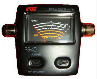
A power meter
NOTE: If your SWR reading is below 1, you have a problem. You might have a bad SWR meter, something wrong with your antenna or antenna connection, or possible have a damaged or defective radio.
When a transmitted wave hits a boundary such as the one between the lossless transmission line and load (Figure 1), some energy will be transmitted to the load and some will be reflected. The reflection coefficient relates the incoming and reflected waves as:
Γ = V-/V+
(Eq. 1)
Where V- is the reflected wave and V+ is the incoming wave. VSWR is related to the magnitude of the voltage reflection coefficient (Γ) by:
VSWR = (1 + |Γ|)/(1 – |Γ|) (Eq. 2)
Figure 1. Transmission line circuit illustrating the impedance mismatch boundary between the transmission line and the load. Reflections occur at the boundary designated by Γ. The incident wave is V+ and the reflective wave is V-.
VSWR can be measured directly with an SWR meter. An RF test instrument such as a vector network analyzer (VNA) can be used to measure the reflection coefficients of the input port (S11) and the output port (S22). S11 and S22 are equivalent to Γ at the input and output port, respectively. The VNAs with math modes can also directly calculate and display the resulting VSWR value.
The return loss at the input and output ports can be calculated from the reflection coefficient, S11 or S22, as follows:
RLIN = 20log10|S11| dB (Eq. 3)
RLOUT = 20log10|S22| dB (Eq. 4)
The reflection coefficient is calculated from the characteristic impedance of the transmission line and the load impedance as follows:
Γ = (ZL - ZO)/(ZL + ZO) (Eq. 5)
Where ZL is the load impedance and ZO is the characteristic impedance of the transmission line (Figure 1).
VSWR can also be expressed in terms of ZL and ZO. Substituting Equation 5 into Equation 2, we obtain:
VSWR = [1 + |(ZL - ZO)/(ZL + ZO)|]/[1 - |(ZL - ZO)/(ZL + ZO)|] = (ZL + ZO + |ZL - ZO|)/(ZL + ZO - |ZL - ZO|)
For ZL > ZO, |ZL - ZO| = ZL - ZO
Therefore:
VSWR = (ZL + ZO + ZO - ZL)/(ZL + ZO - ZO + ZL) = ZO/ZL. (Eq. 7)
We noted above that VSWR is a specification given in ratio form relative to 1, as an example 1.5:1. There are two special cases of VSWR, ∞:1 and 1:1. A ratio of infinity to one occurs when the load is an open circuit. A ratio of 1:1 occurs when the load is perfectly matched to the transmission-line characteristic impedance.
VSWR is defined from the standing wave that arises on the transmission line itself by:
VSWR = |VMAX|/|VMIN| (Eq. 8)
Where VMAX is the maximum amplitude and VMIN is the minimum amplitude of the standing wave. With two super-imposed waves, the maximum occurs with constructive interference between the incoming and reflected waves. Thus:
VMAX = V+ + V- (Eq. 9)
for maximum constructive interference. The minimum amplitude occurs with deconstructive interference, or:
VMIN = V+ - V- (Eq. 10)
Substituting Equations 9 and 10 into Equation 8 yields
VSWR = |VMAX|/|VMIN| = (V+ + V-)/(V+ - V-) (Eq. 11)
Substitute Equation 1 into Equation 11, we obtain:
As the electric wave travels through the different parts of the antenna system (receiver, feed line, antenna, free space) it may encounter differences in impedances. At each interface, some fraction of the wave's energy will reflect back to the source, forming a standing wave in the feed line. The ratio of maximum power to minimum power in the wave can be measured and is called the voltage standing wave ratio (VSWR). A VSWR of less than 1.5:1 is ideal, a VSWR of 2:1 is considered to be marginally acceptable in low power applications where power loss is more critical, although a VSWR as high as 6:1 may still be usable with the right equipment. Just in case you don’t care for mathematical equations, here’s a little “cheat sheet” table to helpunderstand the correlation of VSWR to the percentage of reflected power that will return.
VSWR
Returned Power
(approximate)
1:1
0%
2:1
10%
3:1
25%
6:1
50%
10:1
65%
14:1
75%
2.What cause high VSWR?
If the VSWR is too high, there could potentially be too much energy reflected back into a power amplifier, causing damage to the internal circuitry. In an ideal system, there would be a VSWR of 1:1. Causes of a high VSWR rating could be use of an improper load or something unknown such as a damaged transmission line.