As the gateway between the "real world" analog domain and the digital world composed of 1s and 0s, data converters are one of the key elements in modern signal processing. In the past 30 years, a large number of innovative technologies have emerged in the field of data conversion. These technologies have not only boosted performance improvements and architectural advancements in various fields, from medical imaging to cellular communications, to consumer audio and video, but also played a role in the realization of new applications. Important role.
The continuous expansion of broadband communications and high-performance imaging applications highlights the special importance of high-speed data conversion: The converter must be able to handle signals with a bandwidth ranging from 10 MHz to 1 GHz. People achieve these higher speeds through a variety of converter architectures, each with its own advantages. Switching back and forth between the analog and digital domains at high speeds also poses some special challenges to signal integrity—not only analog signals, but also clock and data signals. Understanding these issues is not only important for component selection, but also affects the overall system architecture choice.
1. Faster
In many technical fields, we are accustomed to associating technological progress with higher speeds: From Ethernet to wireless local area networks to cellular mobile networks, the essence of data communication is to continuously increase the data transmission rate. Through advances in clock rates, microprocessors, digital signal processors, and FPGAs have developed rapidly. These devices mainly benefit from the shrinking size of the etching process, resulting in faster switching speeds, smaller size (and lower power consumption) transistors. These advancements have created an environment where processing power and data bandwidth have grown exponentially. These powerful digital engines have brought the same exponential growth in signal and data processing requirements: from static images to video, to bandwidth and spectrum, whether wired or wireless. A processor running at a clock rate of 100 MHz may be able to effectively process signals with a bandwidth of 1 MHz to 10 MHz: a processor running at a clock rate of several GHz can process signals with a bandwidth of hundreds of MHz.
Naturally, stronger processing power and higher processing rate will lead to faster data conversion: wideband signals expand their bandwidth (often reaching the limits of the spectrum set by physical or regulatory agencies), and imaging systems seek to increase the processing capacity of pixels per second To process higher resolution images faster. The system architecture has been innovated to take advantage of this extremely high processing performance, and there has also been a trend of parallel processing, which may mean the need for multi-channel data converters.
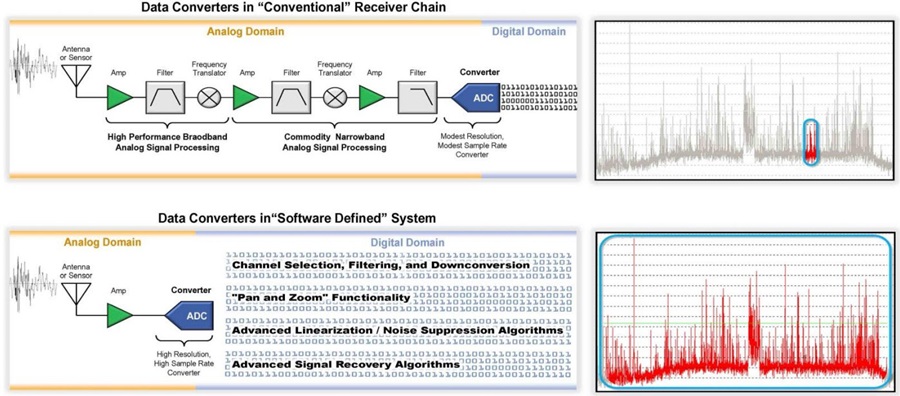
Another important change in the architecture is the trend toward multi-carrier/multi-channel, and even software-defined systems. Traditional analog-intensive systems complete a lot of signal conditioning work (filtering, amplification, frequency conversion) in the analog domain; after adequate preparation, the signal is digitized. An example is FM broadcasting: the channel width of a given station is usually 200 kHz, and the FM band ranges from 88 MHz to 108 MHz. The traditional receiver converts the frequency of the target station into an intermediate frequency of 10.7 MHz, filters out all other channels, and amplifies the signal to the best demodulation amplitude. The multi-carrier architecture digitizes the entire 20 MHz FM frequency band and uses digital processing technology to select and restore target stations. Although the multi-carrier scheme requires a much more complicated circuit, it has great system advantages: the system can recover multiple stations at the same time, including sideband stations. If properly designed, multi-carrier systems can even be reconfigured through software to support new standards (for example, new high-definition radio stations allocated in radio sidebands). The ultimate goal of this approach is to use a broadband digitizer that can accommodate all frequency bands and a powerful processor that can recover any signal: this is the so-called software-defined radio. There are equivalent architectures in other fields-software-defined instrumentation, software-defined camera, etc. We can think of these as virtualized signal processing equivalents. What makes flexible architectures like this possible is powerful digital processing technology and high-speed, high-performance data conversion technology.
2. Bandwidth and dynamic range
Whether it is analog or digital signal processing, its basic dimensions are bandwidth and dynamic range-these two factors determine the amount of information that the system can actually process. In the field of communication, Claude Shannon's theory uses these two dimensions to describe the basic theoretical limits of the amount of information that a communication channel can carry, but its principles are applicable to many fields. For imaging systems, the bandwidth determines the number of pixels that can be processed at a given time, and the dynamic range determines the intensity or color range between the darkest perceptible light source and the saturation point of the pixel.
The usable bandwidth of the data converter has a basic theoretical limit set by the Nyquist sampling theory-in order to represent or process a signal with a bandwidth of F, we need to use a data converter with an operating sampling rate of at least 2 F (please note , This rule applies to any sampling data system-both analog and digital). For actual systems, a certain amount of oversampling can greatly simplify system design, so a more typical value is 2.5 to 3 times the signal bandwidth. As mentioned earlier, increasing processing power can improve the system's ability to handle higher bandwidths, and systems such as cellular phones, cable systems, wired and wireless local area networks, image processing, and instrumentation are all moving towards higher bandwidth systems. This continuous increase in bandwidth requirements requires data converters with higher sampling rates.
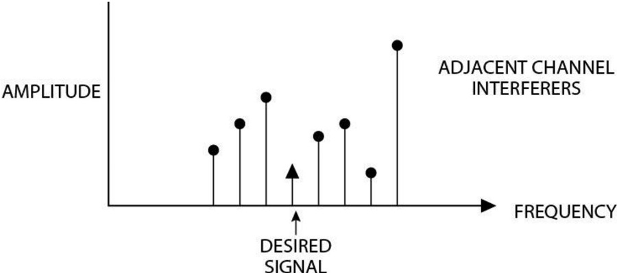
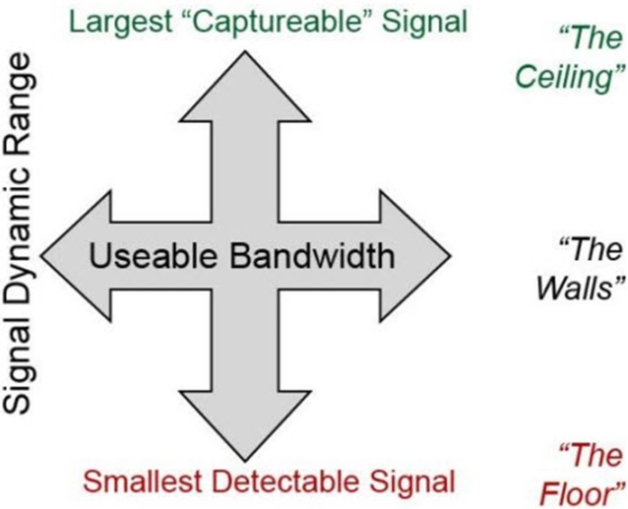
If the bandwidth dimension is intuitive and easy to understand, then the dynamic range dimension may be slightly obscure. In signal processing, the dynamic range represents the distribution range between the largest signal that the system can handle without saturation or clipping and the smallest signal that the system can effectively capture. We can consider two types of dynamic range: the configurable dynamic range can be achieved by placing a programmable gain amplifier (PGA) before the low-resolution analog-to-digital converter (ADC) (assuming that for a 12-bit configurable dynamic range, in a Place a 4-bit PGA before the 8-bit converter): When the gain is set to a low value, this configuration can capture large signals without exceeding the range of the converter. When the signal is too small, the PGA can be set to high gain to amplify the signal above the noise floor of the converter. The signal may be a strong or weak station, or it may be a bright or dim pixel in the imaging system. For traditional signal processing architectures that only try to recover one signal at a time, this configurable dynamic range may be very effective.
The instantaneous dynamic range is more powerful: In this configuration, the system has sufficient dynamic range to capture large signals at the same time without clipping, while also recovering small signals-now, we may need a 14-bit converter . This principle is suitable for many applications-restore strong or weak radio signals, restore cell phone signals, or restore super bright and super dark parts of an image. While the system tends to use more complex signal processing algorithms, the demand for dynamic range is also going to rise. In this case, the system can process more signals-if all signals have the same strength and need to process twice as much signal, you need to increase the dynamic range by 3 dB (under all other conditions being equal). Perhaps more importantly, as mentioned earlier, if the system needs to handle both strong and weak signals at the same time, the incremental requirements for dynamic range may be much larger.
3. Different measures of dynamic range
In digital signal processing, the key parameter of dynamic range is the number of bits in the signal representation, or word length: the dynamic range of a 32-bit processor is more than that of a 16-bit processor. Signals that are too large will be clipped-this is a highly non-linear operation that will destroy the integrity of most signals. Signals that are too small—less than 1 LSB in amplitude—will become undetectable and lost. This limited resolution is often called quantization error, or quantization noise, and may be an important factor in establishing the lower limit of detectability.
Quantization noise is also a factor in a mixed signal system, but there are multiple factors that determine the usable dynamic range of the data converter, and each factor has its own dynamic range
Signal-to-noise ratio (SNR)——The ratio of the converter's full scale to the total noise of the frequency band. This noise may come from quantization noise (as described above), thermal noise (present in all real systems), or other error terms (such as jitter).
Static non-linearity-differential non-linearity (DNL) and integral non-linearity (INL)-a measure of the non-ideal degree of the DC transfer function from the input to the output of the data converter (DNL usually determines the dynamics of the imaging system range).
total harmonic distortion-static and dynamic nonlinearity will produce harmonics, which may effectively shield other signals. THD usually limits the effective dynamic range of an audio system.
Spurious Free Dynamic Range (SFDR)—Considering the highest spectral spurs relative to the input signal, whether it is the second or third harmonic clock feedthrough, or even 60 Hz “humming” noise. Since spectrum tones or spurs may shield small signals, SFDR is a good indicator of the available dynamic range in many communication systems.
There are other technical specifications-in fact, each application may have its own effective dynamic range description method. At the beginning, the resolution of the data converter is a good proxy for its dynamic range, but it is very important to choose the correct technical specifications when making a real decision. The key principle is that more is better. Although many systems can immediately realize the need for higher signal processing bandwidth, the need for dynamic range may not be so intuitive, even if the requirements are more demanding.
It’s worth noting that although bandwidth and dynamic range are the two main dimensions of signal processing, it is necessary to consider the third dimension, efficiency: This helps us answer the question: "In order to achieve additional performance, I need How much does it cost?" We can look at the cost from the purchase price, but for data converters and other electronic signal processing applications, a purer technical measure of cost is power consumption. Higher-performance systems-greater bandwidth or dynamic range-tend to consume more power. With the advancement of technology, we are all trying to reduce power consumption while increasing bandwidth and dynamic range.
4. Main application
As mentioned earlier, each application has different requirements in terms of basic signal dimensions, and in a given application, there may be many different performances. For example, a 1 million pixel camera and a 10 million pixel camera. Figure 4 shows the bandwidth and dynamic range usually required for some different applications. The upper part of the figure is generally referred to as high-speed-converters with a sampling rate of 25 MHz and above can effectively handle bandwidths of 10 MHz or above.
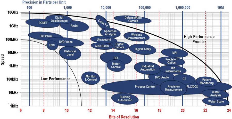
It should be noted that the application diagram is not static. Existing applications may use new, higher-performance technologies to enhance their functions-for example, high-definition cameras or higher-resolution 3D ultrasound equipment. In addition, new applications will emerge every year-a large part of the new applications will be at the outer edge of the performance boundary: thanks to the new combination of high speed and high resolution. As a result, the edge of converter performance continues to expand, just like ripples in a pond.
It should also be remembered that most applications need to pay attention to power consumption: for portable/battery-powered applications, power consumption may be the main technical limitation, but even for line-powered systems, we are beginning to find that signal processing components (analog Whether it is digital or not) power consumption will eventually limit the performance of the system in a given physical area
5. Technological development trends and innovations-how to achieve...
Given that these applications continue to increase the performance requirements of high-speed data converters, the industry has responded to this with continuous technological advancement. Technology pushes advanced high-speed data converters from the following factors:
Process technology: Moore's Law and data converters-The semiconductor industry's continuous advancement of digital processing performance is obvious to all. The main driving factor is the huge progress made in wafer processing technology towards finer pitch lithography processes. The switching rate of deep submicron CMOS transistors far exceeds that of their predecessors, bringing the operating clock rates of controllers, digital processors, and FPGAs to several GHz steps. Mixed-signal circuits like data converters can also take advantage of these advances in the etching process to reach higher speeds by the wind of "Moore's Law"-but for mixed-signal circuits, this comes at a price: more advanced The working power supply voltage of the etching process has a tendency to decrease continuously. This means that the signal swing of the analog circuit is shrinking, increasing the difficulty of maintaining the analog signal above the thermal noise floor: higher speeds are obtained at the expense of reduced dynamic range.
Advanced architecture (this is not the data converter of the primitive age)-While the semiconductor process is developing in great strides, in the past 20 years, there has also been a wave of digital wave innovation in the field of high-speed data converter architecture, in order to achieve higher efficiency with amazing efficiency The bandwidth and the greater dynamic range have made a great contribution. Traditionally, there are a variety of architectures for high-speed analog-to-digital converters, including fully parallel architecture (ash), folding architecture (folding), interleaved architecture (interleaved), and pipeline architecture (pipeline), which are still very popular today. Later, architectures traditionally used for low-speed applications were also added to the high-speed application camp, including successive approximation registers (SAR) and -. These architectures were specifically modified for high-speed applications. Each architecture has its own advantages and disadvantages: some applications generally determine the best architecture based on these trade-offs. For high-speed DACs, the preferred architecture is generally a switched current mode structure, but there are many variations of this type of structure; the speed of the switched capacitor structure is steadily increasing, and it is still very popular in some embedded high-speed applications.
Digital auxiliary method-Over the years, in addition to craftsmanship and architecture, high-speed data converter circuit technology has also made brilliant innovations. The calibration method has a history of decades and plays a vital role in compensating the mismatch of integrated circuit components and improving the dynamic range of the circuit. Calibration has gone beyond the scope of static error correction, and is increasingly used to compensate for dynamic nonlinearity, including setup errors and harmonic distortion.
In short, innovations in these fields have greatly promoted the development of high-speed data conversion.
6. Realize
The realization of broadband mixed-signal systems requires more than just choosing the right data converter-these systems may have stringent requirements on other parts of the signal chain. Similarly, the challenge is to achieve excellent dynamic range in a wider bandwidth range-to get more signals in and out of the digital domain, making full use of the processing power of the digital domain.
—In the traditional single-carrier system, signal conditioning is to eliminate unnecessary signals as soon as possible, and then amplify the target signal. This often involves selective filtering and narrow-band systems fine-tuned for the target signal. These fine-tuned circuits can be very effective in achieving gain, and in some cases, frequency planning techniques can be used to ensure that harmonics or other spurs are excluded from the band. Broadband systems cannot use these narrowband technologies, and achieving wideband amplification in these systems may face huge challenges.
—The traditional CMOS interface does not support data rates much greater than 100 MHz—and the low-voltage differential swing (LVDS) data interface runs at 800 MHz to 1 GHz. For larger data rates, we can use multiple bus interfaces, or use the SERDES interface. Modern data converters use a SERDES interface with a maximum rate of 12.5 GSPS (see JESD204B standard for specifications)-multiple data channels can be used to support different combinations of resolution and rate in the converter interface. The interfaces themselves can be very complicated.
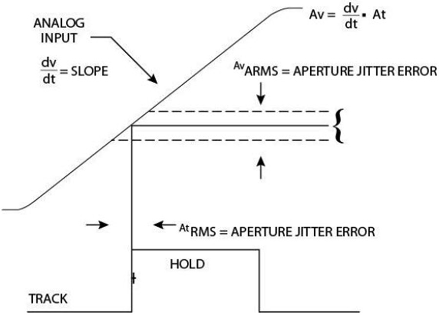
—As far as the quality of the clock used in the system is concerned, the processing of high-speed signals may also be very difficult. The jitter/error in the time domain is converted into noise or error in the signal, as shown in Figure 5. When processing signals with a rate greater than 100 MHz, clock jitter or phase noise can become a limiting factor in the available dynamic range of the converter. Digital-level clocks may not be adequate for this type of system, and high-performance clocks may be required.
The pace toward wider bandwidth signals and software-defined systems is accelerating, and the industry continues to innovate, and innovative methods for building better and faster data converters are emerging, pushing the three dimensions of bandwidth, dynamic range, and power efficiency to a new level.


|
|
|
|
How far(long) the transmitter cover?
The transmission range depends on many factors. The true distance is based on the antenna installing height , antenna gain, using environment like building and other obstructions , sensitivity of the receiver, antenna of the receiver . Installing antenna more high and using in the countryside , the distance will much more far.
EXAMPLE 5W FM Transmitter use in the city and hometown:
I have a USA customer use 5W fm transmitter with GP antenna in his hometown ,and he test it with a car, it cover 10km(6.21mile).
I test the 5W fm transmitter with GP antenna in my hometown ,it cover about 2km(1.24mile).
I test the 5W fm transmitter with GP antenna in Guangzhou city ,it cover about only 300meter(984ft).
Below are the approximate range of different power FM Transmitters. ( The range is diameter )
0.1W ~ 5W FM Transmitter :100M ~1KM
5W ~15W FM Ttransmitter : 1KM ~ 3KM
15W ~ 80W FM Transmitter : 3KM ~10KM
80W ~500W FM Transmitter : 10KM ~30KM
500W ~1000W FM Transmitter : 30KM ~ 50KM
1KW ~ 2KW FM Transmitter : 50KM ~100KM
2KW ~5KW FM Transmitter : 100KM ~150KM
5KW ~10KW FM Transmitter : 150KM ~200KM
How to contact us for the transmitter?
Call me +8618078869184 OR
Email me [email protected]
1.How far you want to cover in diameter ?
2.How tall of you tower ?
3.Where are you from ?
And we will give you more professional advice.
About Us
FMUSER.ORG is a system integration company focusing on RF wireless transmission / studio video audio equipment / streaming and data processing .We are providing everything from advice and consultancy through rack integration to installation, commissioning and training.
We offer FM Transmitter, Analog TV Transmitter, Digital TV transmitter, VHF UHF Transmitter, Antennas, Coaxial Cable Connectors, STL, On Air Processing, Broadcast Products for the Studio, RF Signal Monitoring, RDS Encoders, Audio Processors and Remote Site Control Units, IPTV Products, Video / Audio Encoder / Decoder, designed to meet the needs of both large international broadcast networks and small private stations alike.
Our solution has FM Radio Station / Analog TV Station / Digital TV Station / Audio Video Studio Equipment / Studio Transmitter Link / Transmitter Telemetry System / Hotel TV System / IPTV Live Broadcasting / Streaming Live Broadcast / Video Conference / CATV Broadcasting system.
We are using advanced technology products for all the systems, because we know the high reliability and high performance are so important for the system and solution . At the same time we also have to make sure our products system with a very reasonable price.
We have customers of public and commercial broadcasters, telecom operators and regulation authorities , and we also offer solution and products to many hundreds of smaller, local and community broadcasters .
FMUSER.ORG has been exporting more than 15 years and have clients all over the world. With 13 years experience in this field ,we have a professional team to solve customer's all kinds of problems. We dedicated in supplying the extremely reasonable pricing of professional products & services. Contact email : [email protected]
Our Factory
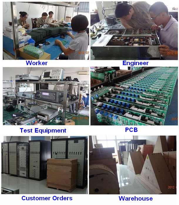
We have modernization of the factory . You are welcome to visit our factory when you come to China.
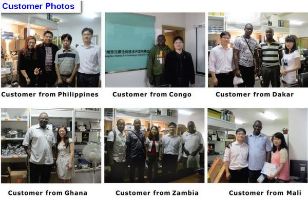
At present , there are already 1095 customers around the world visited our Guangzhou Tianhe office . If you come to China , you are welcome to visit us .
At Fair
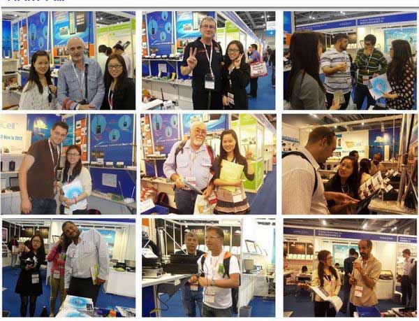
This is our participation in 2012 Global Sources Hong Kong Electronics Fair . Customers from all over the world finally have a chance to get together.
Where is Fmuser ?
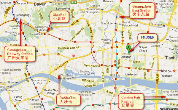
You can search this numbers " 23.127460034623816,113.33224654197693 " in google map , then you can find our fmuser office .
FMUSER Guangzhou office is in Tianhe District which is the center of the Canton . Very near to the Canton Fair , guangzhou railway station, xiaobei road and dashatou , only need 10 minutes if take TAXI . Welcome friends around the world to visit and negotiate .
Contact: Sky Blue
Cellphone: +8618078869184
WhatsApp: +8618078869184
Wechat: +8618078869184
E-mail: [email protected]
QQ: 727926717
Skype: sky198710021
Address: No.305 Room HuiLan Building No.273 Huanpu Road Guangzhou China Zip:510620
|
|
|
|
English: We accept all payments , such as PayPal, Credit Card, Western Union, Alipay, Money Bookers, T/T, LC, DP, DA, OA, Payoneer, If you have any question , please contact me [email protected] or WhatsApp +8618078869184
-
PayPal.  www.paypal.com www.paypal.com
We recommend you use Paypal to buy our items ,The Paypal is a secure way to buy on internet .
Every of our item list page bottom on top have a paypal logo to pay.
Credit Card.If you do not have paypal,but you have credit card,you also can click the Yellow PayPal button to pay with your credit card.
---------------------------------------------------------------------
But if you have not a credit card and not have a paypal account or difficult to got a paypal accout ,You can use the following:
Western Union.  www.westernunion.com www.westernunion.com
Pay by Western Union to me :
First name/Given name: Yingfeng
Last name/Surname/ Family name: Zhang
Full name: Yingfeng Zhang
Country: China
City: Guangzhou
|
---------------------------------------------------------------------
T/T . Pay by T/T (wire transfer/ Telegraphic Transfer/ Bank Transfer)
First BANK INFORMATION (COMPANY ACCOUNT):
SWIFT BIC: BKCHHKHHXXX
Bank name: BANK OF CHINA (HONG KONG) LIMITED, HONG KONG
Bank Address: BANK OF CHINA TOWER, 1 GARDEN ROAD, CENTRAL, HONG KONG
BANK CODE: 012
Account Name : FMUSER INTERNATIONAL GROUP LIMITED
Account NO. : 012-676-2-007855-0
---------------------------------------------------------------------
Second BANK INFORMATION (COMPANY ACCOUNT):
Beneficiary: Fmuser International Group Inc
Account Number: 44050158090900000337
Beneficiary's Bank: China Construction Bank Guangdong Branch
SWIFT Code: PCBCCNBJGDX
Address: NO.553 Tianhe Road, Guangzhou, Guangdong,Tianhe District, China
**Note: When you transfer money to our bank account, please DO NOT write anything in the remark area, otherwise we won't be able to receive the payment due to government policy on international trade business.
|
|
|
|
* It will be sent in 1-2 working days when payment clear.
* We will send it to your paypal address. If you want to change address, please send your correct address and phone number to my email [email protected]
* If the packages is below 2kg,we will be shipped via post airmail, it will take about 15-25days to your hand.
If the package is more than 2kg,we will ship via EMS , DHL , UPS, Fedex fast express delivery,it will take about 7~15days to your hand.
If the package more than 100kg , we will send via DHL or air freight. It will take about 3~7days to your hand.
All the packages are form China guangzhou.
* Package will be sent as a "gift" and declear as less as possible,buyer don't need to pay for "TAX".
* After ship, we will send you an E-mail and give you the tracking number.
|
|
|
For Warranty .
Contact US--->>Return the item to us--->>Receive and send another replace .
Name: Liu xiaoxia
Address: 305Fang HuiLanGe HuangPuDaDaoXi 273Hao TianHeQu Guangzhou China.
ZIP:510620
Phone: +8618078869184
Please return to this address and write your paypal address,name,problem on note: |
|