Electronic tube transmitter circuit diagram (1)
This article introduces a transmitter assembled with 6Pl power amplifier tube.
The circuit is shown in the figure below: B1, B2, G, R1, R2, C2, C3, C4, and C5 are all disassembled products. Because the power supply filter capacitor in the machine is too large, a color TV filter capacitor is used. L1 selects 22mm enameled wire to wind 100 turns on the magnetic ring of MX-2000. L2 determines the transmitting frequency of the station. If the frequency is selected in the medium wave band, L2 can use 35mm enameled wire with 30+50 turns on the medium wave magnet, or select 13mm enameled wire to close 90 turns on a 25mm paper tube. In this way, the emission frequency will fall between 550-1650kHz. If the short-wave band is selected, L2 can be wound 9 turns between a 16mm paper tube with 0.5mm enameled wire. The frequency of the oscillator thus constituted falls between 6 and 18 MHz. C5 is air duplex with a capacity of 360pFx2. B1 is the original machine power transformer. The high-voltage part rectifier uses 4 IN4007 instead. B2 is the original output transformer. C2 and C3 are mica capacitors that are disassembled in the machine, and the withstand voltage of C2 and C3 is better than 400V. R1 and R2 can also buy cement resistors by themselves. Due to the large power dissipation, the power should be ≥IW. TX is a 1/4 antenna, which can be replaced by a section of thick wire, ‘the length is about 1/4 of the emission wavelength. What the author chooses is 3mm, 8m long enameled wire. The whole circuit installation does not need to use copper-clad board, directly use a piece of bakelite board, drill on it. Hole, scaffold welding can be done. As long as the components are good, the circuit will vibrate after installation. When vibrating, a light blue electron flow can be seen in G, accompanied by a "sizzling" sound.
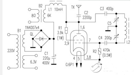
If you have the conditions, you can make a simple field strength meter, and adjust R2 to maximize the launch field strength. The antenna can be installed vertically on the wall through an insulator. After connecting the antenna, input a 5W audio signal at B2 to extend the distance between a radio and the transmitter. The radio should receive the signal clearly, and the distortion should not be obvious. If the hum is too loud during launch, grounding can solve it. After actual measurement, the transmitting power is as large as 4.5W.
Electronic tube transmitter circuit diagram (2)
This is a low cost and easy to build low power FM transmitter. The range of the FM transmitter takes away about 300 kilometer 9V power supply while running. The range claims will increase by approximately 400 feet when running on a 12V power supply. It should be noted that this transmitter should not be used as a room or phone bug.
List of components:
C1=1nF
C2=5.6pF
C3, C4=10UF/16V
C5=3-18PF Hua Gao/variable capacity
R1=270 ohm 1/4W
R2, R5, R6=4.7K1/4W
R3=10K1/4W
R4=100K1/4W
Q1, Q2=2N2222A2N3904 or NTE123A
L1, L2=5 open the air core coil
MIC=Electret microphone
MISC: 9V battery management unit, PC board, steel wire antenna.
Electronic tube transmitter circuit diagram (3)
Four-lamp electronic tube transmitter circuit
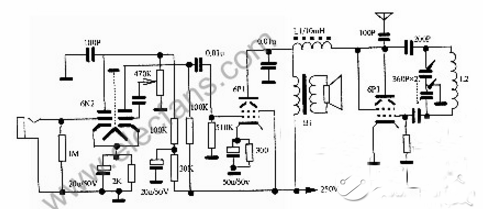
This machine has simple circuit, stable work and good performance. The required components can be purchased from the market. It can be used for classroom teaching and demonstration, and it can also broadcast records or short-distance communication. It has less distortion and better frequency response characteristics.
This machine includes audio amplifier and oscillation and two parts. The audio amplifier is composed of voltage amplifier and power amplifier. The dual triode 6N2 and the beam tetrode 6P1 are used respectively, and the oscillation part is also served by 6P1.
The audio signal is input from the grid of the electron tube G1 (6N2), after being amplified twice, it is sent to the power amplifier stage G2 (6P1). The strength of the signal sent can be controlled by a 470K potentiometer. The amplified audio signal and high-frequency oscillation signal are oscillating The screen of the G3 (6P1) tube is mixed so that the high-frequency oscillating current carries the audio signal to be transmitted through the antenna. If you don't need to monitor, you can replace the field sounder Y and connect a 3.5 ohm resistor to the B1 secondary.
Our other product:


