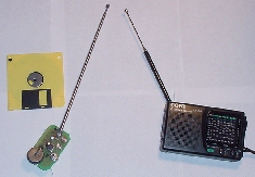
 The photo shows a wireless FM transmitter, pocket radio and yellow disk for size comparisons. Speak into the transmitter and others hear you on any FM radio. The transmitter can be built in an afternoon with simple, affordable and widely available parts. Construction is fun and much can be learned although performance is modest; for example, your voice gets difficult to hear at distances greater than 25 feet.
Motivation and Audience
Our long-term goals with such circuits are in remote control and data acquisition. Touch tones could be transmitted to wirelessly turn on/off a robot's actuators. Sensor data could be converted into morse-code like sounds and deciphered by a microcontroller to wirelessly monitor environments. This tutorial's audience would be also motivated by such applications. Building a simple FM transmitter would be a first-step towards such goals.
Not to give you false expectations, this FM transmitter is far from perfect offering only modest performance. First, tuning the transmitter can be frustrating. Even slight turns in the variable capacitor can result in large frequency changes. Second, transmitter tuning often resulted in a harmonic frequency. Instead of the intended 108 MHz for example, capacitor tuning yielded a 216 MHz transmitter frequency. In addition to hearing your voice one could slightly hear radio station broadcasts.
If performance is modest, why would I build this transmitter?
One answer is that much can be learned and this tutorial is is appendixed with the underlying mathematics to calculate parameters like (1) tranmitter frequency, power output and range (2) antenna length and (3) required coil winding. Often on the web, one just finds a schematic. By adding the analysis (with high school level math), one can conceive improvements on transmitter performance.
This tutorial's audience is thus electronics enthusiasts who:
- don't have much FM or radio-frequency (RF) experience
- want to build an FM transmitter
- want to learn how such transmitters work
- want to learn how components are selected e.g. calculating the number of turns when building an air coil, antenna length etc.
Again this tutorial emphasizes that the transmitter's performance is modest, but is learned in its construction. The tutorial breakdown is as follows:
- Parts List and Sources
- Construction/Schematic
- Theory
- Operation
- Where To Go From Here
- Author Information
Parts List and Sources
US-based vendors include Jameco, Digikey, JDR and Radio Shack. Note: Boondog has no association with these vendors. Attempts were acquire all parts from a single vendor. Part numbers for common resistors are not given.
TABLE 1: FM TRANSMITTER PARTS
| PART DESCRIPTION |
VENDOR |
PART |
PRICE (1999) |
QTY |
| 2N2222 (TO-18 CAN CASE) NPN TRANSMITTER |
JAMECO |
38236 |
0.39 |
1 |
|
| ELETRET MIC 4.5V LOW IMPEDENCE |
JAMECO |
136573 |
0.75 |
1 |
|
| 4 TO 30 PF VARIABLE CAPACITOR |
JAMECO |
32838 |
0.99 |
1 |
|
| SPST SWITCH |
JAMECO |
76523 |
1.09 |
1 |
|
| BR2325 3V COIN CELL |
JAMECO |
11789 |
1.95 |
2 |
|
| BATTERY HOLDER FOR TWO CR2325 CELLS |
JAMECO |
38543 |
0.66 |
1 |
|
| 10 KOHM RESISTOR |
|
|
|
2 |
|
| 4.7 KOHM RESISTOR |
|
|
|
1 |
|
| 47 OHM RESISTOR |
|
|
|
1 |
|
| 10 UF ELECTROLYTIC CAP |
JAMECO |
158529 |
0.09 |
1 |
|
| 0.01 UF CERAMIC CAP |
JAMECO |
15229 |
0.05 |
1 |
|
| PROTOTYPING BOARD 1.6X2.7 SQ.IN |
JAMECO |
105099 |
4.95 |
1 |
|
| 4.7 PF CERAMIC CAP |
RADIO SHACK |
272-120 |
0.49 |
1 |
|
| (OPTIONAL) 34.75 INCH TELESCOPIC ANTENNA |
RADIO SHACK |
270-1402 |
3.99 |
1 |
|
| (OPTIONAL) MAGNET WIRE 22 GAUGE |
RADIO SHACK |
278-1345 |
3.99 |
1 |
|
| SODA STRAW |
McDONALD'S |
|
FREE |
1 |
|
| |
An effort was made to find a single source supplier of all parts. Jameco has almost every part cited in the tables. Details construction your air core inductor using a McDonald's soda straw will be described in the next section.
Construction
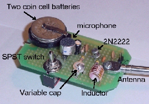
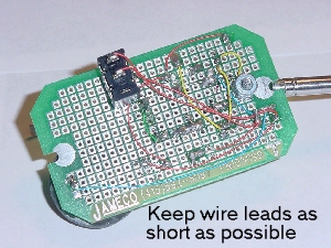
A combination of wirewrapping and soldering was used to construct the FM transmitter. Jameco's prototyping card provides enough room for (non-critical) part placement. You should try to keep all parts close together and keep wire leads short. The photos below illustrate possible part placement (left) and the solder side (right).
Schematic
fmTx031402a.pdf is the Acrobat file of the same schematic. You will need Adobe's free Acrobat reader to view it.
The schematic and constructing the circuit are relatively straight-forward. Some highlights and clarifications towards circuit construction are given next.
Electret Microphone
An electret microphone has two pins which connect to the positive and negative leads of a battery. As shown in the drawing below, one looks at the bottom of the electret microphone. The pad that physically touches the microphone's casing connects to the battery's negative lead.
Batteries
You can replace the coin cells, typically found in calculators and watches, with regular 1.5V AA, C or D-cells. The coin cells however take less room and can solder onto the protoboard.
2N2222A Transistor
The 2N2222A is a very common NPN transistor. The one used here (Jameco #38236) is the metal can type (TO-18 casing). Its three pins are for the transistor's base (B), collector (C) and emitter (E). There is no standard pinout for transistors. As such, request the transistor's spec sheet when ordering it to identify the pinout, or if you own a multimeter with a transistor tester, use it.
The 2N2222A also comes in a black plastic casing (TO-92 style) which you can use if you want. The T0-18 is preferred because the can has a small tab that typically represents the emitter pin.
Make sure you correctly identify the 2N2222A's pinout and correctly wire the base, collector and emitter in the schematic. Often, circuit malfunctions because the pins were mis-wired.
Variable Capacitor
The leads for the variable capacitor do not fit in normal 0.1 inch protoboards. You can dremel-drill into the protoboard to make the leads fit. Alternatively you can solder wire to the leads, but if you do, keep wires as short as possible in order to avoid stray capacitances.
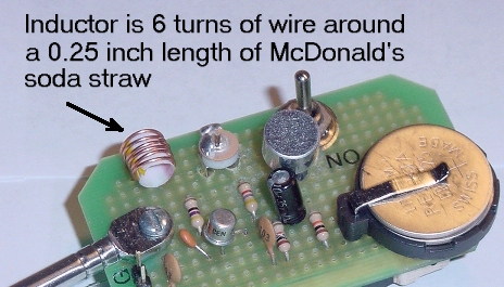
Inductor
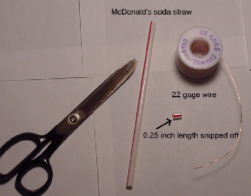
An inductor is just a coil of wire and you need to wind one for this circuit. An inductor is characterized by its length, radius and the number of turns of wire in the coil. Magnet wire (Radio Shack part 278-1345) was used to build the inductor but you can use standard solid strand 22 AWG gauge copper wire.
Some on-line and printed articles describe winding the wire around a pencil. Unfortunately, pencils come in different diameters and hence a McDonald's soda straw was used; the yellow-red-white striped straw, found in every McDonalds in the world, is the same size. The straw's radius is exactly 0.1325 inches (diameter = 0.2650 inches) and 1/4 inches was snipped off the straw.
Next, a straight piece wire was wound around this 1/4 inch snippet six times and then soldered on the prototyping board. The end result is an inductor (also known as an air core coil) with an 0.1325 inch radius. If you wish, you can apply some womens' clear fingernail polish to permanently keep the wire on the straw snippet.
Antenna
A 30 inch long piece of 22 gauge solid stramd copper wire is a suitable antenna. However when carrying the transmitter, you risk tangling the wire. As such you can screw a telescopic antenna, like ones found a radios, into the prototyping board.
Theory: How does the FM Transmitter Work?
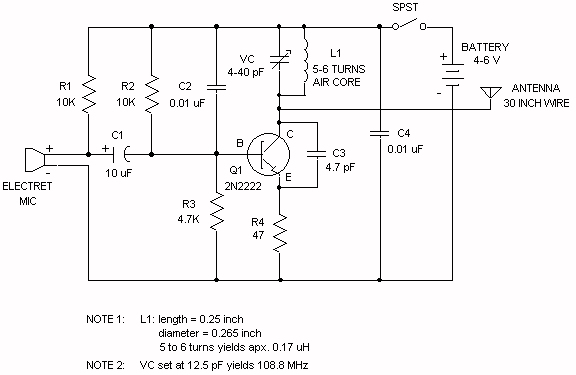
The variable capacitor and your self-made inductor will vibrate at frequencies in the FM radio band (88 to 108 MHz). The electret microphone has a resistance that depends on how loudly you speak into it. This microphone is battery powered and according to the V=IR Ohm's Law, changes in resistance for fixed voltage will result in proportional changes in current. This current feeds into the base of the 2N2222 NPN transistor which is connected to your variable capacitor, inductor and antenna. The net effect is that depending on your variable capacitor's value, your voice will be modulated to transmit at a frequency between 88 and 108 MHz. If a nearby pocket FM radio is tuned to this frequency, you'll be heard when speaking into your transmitter.
The component values in the circuit are derived to better understand how this FM transmitter will work. The underlying math is rather simple and can be found in most undergraduate university physics textbooks.
Inductance of an Air Core Coil
Your self-made inductor has a value determined by its radius r, length x and number of wire turns n.
For your McDonald's soda straw inductor, r = 0.1325 inches, x = 0.25 inches and n = 6 turns and results in L = 0.171 microHenry or 0.000000171 Henry.
The specific frequency f generated is now determined by the capacitance C and inductance L measured in Farads and Henry respectively:
Resonant Frequency of a Parallel LC Circuit
FM radio stations operate on frequencies between 88 and 108 MHz. The variable capacitor and your self-made inductor constitute a parallel LC circuit. It is also called a tank circuit and will vibrate at a resonant frequency which will be picked up your pocket FM radio.
In tank circuits, the underlying physics is that a capacitor stores electrical energy in the electric field between its plates and an inductor stores energy in the magnetic field induced by the coil winding. The mechanical equivalent is the energy balance in a flywheel; angular momentum (kinetic energy) is balanced by the spring (potential energy). Another example is a pendulum where there's a kinetic versus potential energy balance that dictates the period (or frequency) of oscillations.
Given your variable capacitor ranges from 4 to 34 pF, your tank circuit will resonant between 66 and 192 MHz, well within the FM radio range. To compute these values for different values of C, n, r and x a simple Excel spreadsheet, called calcFreq.xls was created. Simply enter the values and the inductance and frequency are automatically calculated.
Antenna Length
You built your antenna either with a piece of solid strand 22 gauge wire 30 inches long or used a telescopically extendable antenna. Its length should be approximately 1/4 the FM wavelength; recall that multiplying frequency and wavelength equals the speed of light. You'll most probably be operating your transmitter near 108 MHz, as such:
Fixed Capacitors
Referring to the schematic, C2 and C4 act as decoupling capacitors and typically 0.01 uF (or 0.1 uF) are used. C4 attempts to maintain a constant voltage across the entire circuit despite voltage fluctuations as the battery dies.
A capacitor can be thought of as a frequency-dependent resistor (called reactance). Speech consists of different frequencies and the capacitor C1 impedes them. The net effect is that C1 modulates the current going into the transistor. Using a large value for C1 reinforces bass (low frequencies) while smaller values boost treble (high frequencies).
The C3 capacitor across the 2N2222A transistor serves to keep the tank circuit vibrating. In theory, as long as there is a supply voltage across the parallel inductor and variable capacitor, it should vibrate at the resonant frequency indefinetely. In reality however, the frequency decays due to heating losses. C3 is used to prevent decay and the 2N2222A spec sheet suggests a capacitance between 4 to 10 pF.
Resistor for Electret Mic
The spec sheet for the Jameco #136573 electret microphone says the maximum current is 0.5 mA. When battery powered at 6V, then the voltage drop across R1 is V1 = 1.92V. The resulting current through the microphone is below the rated maximum since
I1 = (6-1.92)V / 10000 Ohms = 0.41 mA
Resistors and the 2N2222A
The 2N2222A transistor has rated maximums thus demanding a voltage divider made with R2 and R3 and emitter current limiting with R4.
The 2N2222A's maximum rated power is Pmax = 0.5 W. This power ultimately affects the distance you can transmit. Overpowering the transistor will heat and destroy it. To avoid this, one can calculate that the FM transmitter outputs approximately 124 mW and is well below the rated maximum. The mathematical details are given in rfMath.pdf.
The power is intimately related to the transmission range. At 124 mW and 30% radiation efficiencies, the maximum distance between your FM transmitter and a battery-powered radio will range betweem 35 to 112 feet. The calculations are given in rfDistance.pdf.
Operation
First, use a battery-powered pocket radio as a receiver. AC powered boom-boxes and home stereos (110 or 220 V) are not recommended; battery-powered radios are much better at receiving transmissions than AC-powered units.
- Tune your radio to dead air, i.e. frequencies within the FM radio band that are silent or only have some hiss. Frequencies near 108 MHz are typically dead air. The Radio-Locator web page lists local radio stations in your area. This can help you identify dead air frequencies.
- Turn on your FM transmitter, extend its antenna and keep the transmitter approximately 2 feet away from your FM radio. Speak into the mic while slowly adjusting the variable cap. Use your fingernail or non-metallic screwdriver until you hear yourself over the radio. This process is frustratingly tedious, requiring careful capacitor tuning. You are tuned once you hear howling (also known as a hot mic) which indicates transmitter-receiver feedback.
- Increase the transmitter-to-radio distance. Congratulations - you have a wireless microphone!
Where To Go From Here
As stated earlier, performance is modest. The author's experience operating in a major city (Philadelphia, USA) with the battery-powered radio tuned at 108 MHz yielded approximately 25 feet indoors and 50 feet outdoors. Also, in addition to the author's voice, radio station broadcasts could be slightly heard.
To tweak performance, a spectrum analyzer can be used. It's a device that visually displays frequencies are most predominant. The author discovered the circuit was transmitting at approximately 200 to 220 MHz, rather than the desired 108 MHz! 216 MHz is a harmonic, being twice the desired 108 MHz. Transmission range is thus reduced and susceptible to noice (radio station broadcasts).
To transmit at the desired 108 MHz, the author considered the following:
- A hand-made coil that's 0.1 uH is difficult to test. Inductance meters to measure at the micro Henry range are expensive.
- Capacitance meters measuring picoFarads are also expensive.
- A 0.111 uH air core coil was purchased from Coilcraft, an inductor manufacturer.
- Spectrum analyzers costs thousands of dollars. A viable alternative is an $130 USD Elenco F-2800 frequency counter. This is a nice unit to acquire if you plan on building FM transmitters more seriously.
For the most part, the frequency counter displayed approximated 200 MHz even with the Coilcraft inductor! Thus most probably the variable capacitor is not truly giving a 4-to-34 pF range. Since the transmission frequency stayed closed to 200 MHz, calcFreq.xls reveal that variable capacitor actually stays close 4 pF rather than going up to the rated 34 pF. This should be expected since tolerances in capacitance are rarely precise. The net effect is that without picoFarad resolution capacitance you'll be transmitting at a 216 MHz harmonic yielding reduced range and susceptible to noise.
Final Words
This tutorial along with appendixes detail fully a single transistor FM transmitter construction and underlying math. The circuit can be built in an afternoon with less than $10 USD of common parts, resulting in a 25 to 50 foot transmission range.
Like the author, readers might be excited about the prospects of building FM transmitters. Many circuit designs and schematics exist on-line and in print but don't often provide much analysis. This tutorial attempts to fill this gap, especially for first-time FM transmitter builders. The analysis allows one to learn what roles and their values play in the circuit. Such analysis provides a reader a stepping point towards improving or customizing the circuit.
Illustrating the math and real-world operation is the tutorial's value. Some material towards learning more might be acquired from the references below. Happy building!
Our other product: