Frequency Modulation (FM) radio has been used for high-fidelity music and voice broadcasting for many years. It can provide excellent sound quality, signal robustness and noise immunity. Recently, FM radio has been increasingly used in mobile and personal media players. However, the traditional FM design method requires a very long antenna, such as a wired headset, which limits many users who do not have a wired headset. In addition, with the continuous popularity of wireless usage models in portable devices, more users can benefit from wireless FM radios that use other types of FM antennas, and at the same time can use wireless headphones or speakers to listen to sounds.
This article will introduce an FM radio receiver solution that integrates or embeds the antenna inside the portable device, making the headphone cable an option. We start with maximizing the receiving sensitivity, and then introduce methods to maximize the sensitivity, including maximizing the efficiency of the resonance frequency, maximizing the antenna size, and using a tunable matching network to maximize the efficiency of the entire FM bandwidth. Finally, this article will give the realization method of tunable matching network.
Maximum sensitivity
Sensitivity can be defined as the smallest signal that the FM receiving system can receive while achieving a certain level of signal-to-noise ratio (SNR). This is an important parameter of the performance of the FM receiving system, which is related to the signal and noise. The Received Signal Strength Indicator (RSSI) only points out the RF signal strength at a specific tuning frequency point. It does not provide any information about noise or signal quality. When comparing receiver performance under different antennas, the audio signal-to-noise ratio (SNR) may be a better parameter. Therefore, it is very important to maximize SNR to bring a high-quality audio experience to the listener.
The antenna is a bridge connecting the radio frequency circuit and electromagnetic waves. As far as FM reception is concerned, the antenna is a converter that converts energy from electromagnetic waves into voltage that can be used by electronic circuits (such as low noise amplifiers (LNA)). The sensitivity of the FM receiving system is directly related to the voltage received by the internal LNA. To maximize sensitivity, this voltage must be increased as much as possible. There are various antennas on the market, including earphones, short whips, loops and chip antennas, but all antennas can be analyzed with equivalent circuits. Figure 1 shows a general equivalent antenna circuit model:
In Figure 1, X can be a capacitor or an inductor. The choice of X depends on the antenna topology, and its electrical (inductive or capacitive) value is related to the antenna geometry. The loss resistance Rloss is related to the power dissipation in the form of heat energy in the antenna. The radiation resistance Rrad is related to the voltage generated from electromagnetic waves. For ease of explanation, the following text will take the loop antenna model as the analysis object. The same calculation can also be used for other types of antennas, such as short monopole antennas and earphone antennas.

Figure 1: Antenna equivalent circuit model.
Maximize the efficiency of the resonance frequency point
In order to maximize the energy converted by the antenna, a resonant network can be used to offset the reactive impedance of the antenna, and this impedance will attenuate the voltage value conducted by the antenna to the internal LNA. For inductive loop antennas, the capacitor Cres is used to make the antenna resonate at the desired frequency:

The resonance frequency refers to the frequency point at which the antenna converts electromagnetic waves into voltage with the highest efficiency. Antenna efficiency is the ratio of the power on Rrad to the total power received by the antenna, which can be expressed as Rrad/Zant, where Zant is the impedance of the antenna with the antenna resonance network. Zant is expressed as:

When the antenna is in resonance, the efficiency η can be expressed as:

The efficiency at other frequency points is:

The antenna efficiency η at the non-resonant frequency point is lower than the maximum efficiency ηres, because the antenna input impedance Zant at this time is either capacitive or inductive.
Maximize antenna size
In order to recover the transmitted radio frequency signal, the antenna must collect as much energy as possible from the electromagnetic wave, and efficiently convert the electromagnetic wave energy into a voltage through Rrad. The amount of energy collected is limited by the available space and size of the antenna used by the portable device. For a traditional earphone antenna, its length can reach a quarter wavelength of the FM signal, and enough energy can be collected and converted into a voltage that can be used by the internal LNA. In this case, maximizing antenna efficiency is not so important.
However, as portable devices are becoming smaller and thinner, the space left for embedded FM antennas has become very limited. Although the antenna size has been increased as much as possible, the energy collected by the embedded antenna is still very small. Therefore, it becomes very important to improve the antenna efficiency η without sacrificing performance and using a smaller antenna.
Utilize adjustable matching network to maximize the efficiency on the FM frequency band
The frequency range of the FM broadcasting band in most countries is 87.5MHz to 108.0MHz. The frequency band of FM broadcasting in Japan is 76MHz to 90MHz. In some Eastern European countries, the FM radio frequency band is 65.8MHz to 74MHz. In order to adapt to all FM frequency bands in the world, the FM receiving system needs a 40MHz bandwidth. The traditional solution is usually to tune the antenna to the center frequency of the FM band. However, as the above formula shows, the efficiency of the antenna system is a function of frequency. The efficiency reaches its maximum at the resonance point. When the frequency deviates from the resonance frequency, the efficiency will decrease. It is worth noting that since the bandwidth of the global FM frequency band reaches 40MHz, the antenna efficiency will decrease significantly when the frequency is far from the resonance frequency point. For example, if a fixed resonant frequency is set to 98MHz, high efficiency can be achieved at this frequency point, but the efficiency of other frequency points will be significantly reduced, thereby degrading the frequency modulation performance far away from the resonant frequency point. Figure 2 shows the efficiency curves of two antennas (earphone antenna and short antenna) when the fixed resonant frequency is in the center of the frequency band (98MHz).

Figure 2: Typical fixed resonant antenna performance in the FM band.
As can be seen from the above figure, the 98MHz point can achieve the best efficiency, but the closer the frequency is to the edge of the band, the more the efficiency drops. This is not a big problem for earphone antennas, because the size of this antenna can collect enough electromagnetic energy in the entire frequency and convert it to a higher voltage to the RF receiver. However, compared with the longer earphone antenna, the short antenna is small in size and collects less energy, so the efficiency will decrease rapidly when the frequency is far from the resonance point, that is to say, the reception at the edge of the band will occur when the fixed resonance scheme is used. The main problem is that short antennas have a higher "Q" value than earphones, which causes a steep drop in efficiency at the edge of the frequency band.
Q refers to the quality factor, which is proportional to the ratio of the energy stored in the antenna network per unit time to the loss or radiation energy. For the above antenna equivalent circuit with antenna resonance network, the Q value satisfies:
Compared with the short antenna, the earphone antenna has a larger size, so it has a higher radiation resistance Rrad, which leads to a lower Q value. Since embedded applications require the use of short antennas with high Q values, the problem of steep drops in efficiency is very prominent.
The Q value of the antenna is also related to the antenna bandwidth, and its relationship can be expressed as:

Where ƒc is the resonant frequency ƒc, and BW is the 3dB bandwidth of the antenna. Compared with a longer earphone antenna, a short antenna with a high Q value has a smaller bandwidth, so the loss at the edge of the frequency band is larger.
In order to overcome the bandwidth limitation of the high-Q fixed resonant antenna, a self-tuning resonant circuit can be used to change the "fixed resonance" to "adjustable resonance", so that the circuit is always at the resonance frequency point, thereby maximizing the receiving sensitivity. A self-tuning resonant antenna can obtain a higher signal-to-noise ratio, because the gain from the resonant antenna can reduce the system noise figure of the receiver, and the inherent high Q value of the embedded antenna helps to filter out possible harmonics with the local oscillator Disturbance mixed together.
Realization of adjustable matching network
Figure 3 shows the conceptual block diagram of the enhanced FM receiver architecture supporting embedded short antennas. "Adjustable resonance" is realized by on-chip adjustable varactor diode and tuning algorithm.

Figure 3: Conceptual block diagram of Si4704/05.
The above design uses a mixed-signal digital low-IF architecture with a digital signal processor (DSP) to realize advanced signal processing algorithms including self-tuning of embedded short antennas. The antenna algorithm automatically adjusts the capacitance value of the varactor diode according to each frequency tuning point of the device to obtain the best performance.
For example, if the user tunes to 101.1MHz (station 1 in Figure 4), the antenna algorithm will tune the antenna circuit resonance point to 101.1MHz, thereby optimizing the antenna efficiency and reception performance at 101.1MHz. When the user tunes to 84.1MHz (station 2 in Figure 4), the antenna algorithm retunes the resonance point of the antenna circuit to optimize the receiving performance at 84.1MHz.
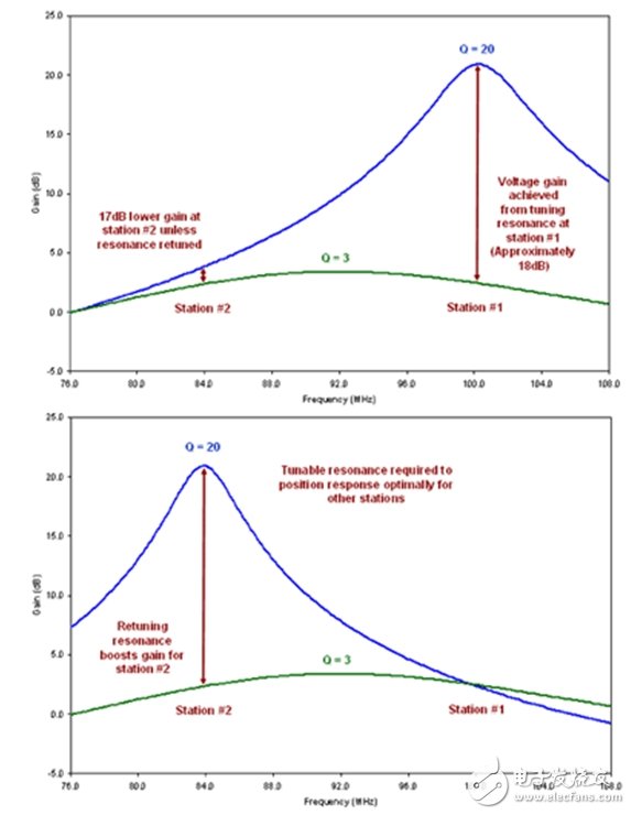
Figure 4: Benefits of adjustable resonance.
Using the adjusted frequency to tune the antenna resonance point can provide maximum efficiency at each given frequency point, thereby maximizing the received signal strength on the entire frequency modulation frequency band. After adopting the adjustable resonant circuit, the performance of the system using the embedded antenna has been improved in the whole frequency band. The resonant antenna at the designated frequency point can also attenuate the interference of other frequency points, thereby significantly improving the selectivity of the receiver. Therefore, the user of the receiver with this embedded antenna can be better protected from other accidental interference sources. . This is especially important in urban areas where the FM band is crowded.
Summary of this article
As the wireless usage model becomes more and more popular in portable devices, more users want to use wireless FM radios with embedded antennas while listening to programs with wireless headphones or speakers. This article discusses the principle of maximizing sensitivity to improve FM reception using embedded antennas, and further discusses how to implement it. Since the available space on portable devices that use embedded antennas is very limited, a self-tuning resonance network can be considered to maximize the sensitivity of the receiver over the entire FM band, so as to keep the short antenna with maximum efficiency at each frequency point.
Our other product:


