Ndërrimi i furnizimit me energji elektrike transmetuesit FM 
With the switching power supply technology continues to mature, further broadening the application field. Switching power supply and continuous power supply compared to the traditional series, the efficiency of electromagnetic pollution, size and reliability, have been greatly improved. On the other hand, the latest solid-state FM transmitters on the power requirements are high, switching power supply technology to mature, and evolving components, high reliability control chip can satisfy the requirements of FM radio transmitter. Solid state FM transmitter in the current incentive and power amplifier components such as switching power supply commonly used as an energy support. The future of digital control and management of the switching power supply put forward higher requirements, intelligent, digital, small size and high reliability will be the FM radio transmitter switching power supply development.
Switching Power Supply
Power is the power FM radio transmitter heart. Taking into account the launch of room between the electromagnetic compatibility of various devices, the overall efficiency of the transmitter, power supply reliability and routine maintenance and other issues, switching power supply is solid state FM transmitter is undoubtedly the best choice for power supply. Superior characteristics of switching power supply is mainly reflected in the following areas. First: smaller. It can be integrated with the power amplifier assembly. Several hundred kHz switching frequency allows filtering device size shrunk to the minimum impedance, thus reducing both the weight of a reduced volume of the transmitter, easy to transport and daily maintenance. Second: more efficient. Including the power switch MOSFET devices and other new applications, multi-topology switching power supply switching technology portfolio to reduce losses and improve power system efficiency of an important guarantee. Third: less electromagnetic pollution. Transmitter equipped with electromagnetic interference (EMI) filter circuit and the associated high peak pulse power of the current absorption circuit is an important guarantee for harmonics to meet the requirements, it can not only improve the load characteristics of power on the grid to reduce the serious to the power grid pollution, but also to other network equipment can reduce harmonic interference. Fourth: to further improve reliability. Lightning protection, anti-induction or counter the over-voltage protection and use of a variety of three anti-paint coating (moisture, salt and mildew) printed circuit board failure probability can be reduced to a minimum.
Switching Power Supply Applications
Switching power supply to a certain frequency through the continuous control of the power switch to on-off operation, so that by the energy storage components (such as inductors and capacitors) to provide power to the converter or load power form. Just by changing the duty cycle, switching frequency or related phase, the average output voltage or current can be controlled. Switching power supply switching frequency range from 20kHz to several MHz. For the power greater than 90W of power in the workplace, switching power supply is usually taken two transformation methods. The power factor correction (PFC) control the converter and DC / DC converter. Special mention should be made here is the power factor correction circuit. It is to ensure that the input voltage and current work with the phase set. The result is a power factor close to 1, depending on the power of all converted to active power, and therefore the system efficiency is improved. If no PFC correction circuit, input current peak value will narrow pulse width switching power supply input pulses to cause serious interference harmonic components. These harmonic components not only failed to provide any energy to the load, but also lead to heat transformers and other equipment. Power factor correction circuit is divided into two types of active and passive. FM radio transmitters were powered by switching power supply circuit of active power factor correction, it is by an active power factor correction of AC / DC converter and an independent DC / DC converter composed of two parts. AC / DC converter include: EMI filters, slow-start circuit, bridge rectifier, PFC controller, drive circuit and the converter circuit (by the power switch MOSFET, energy storage inductor L, fast recovery rectifier diode and filter capacitor etc.), the circuit diagram in Figure 1.
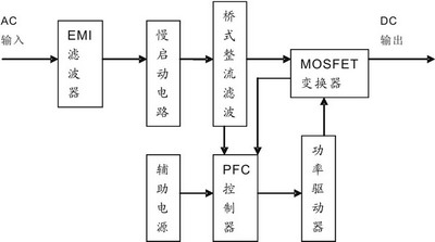
Figure 1 AD / DC converter circuit
AC input EMI filter circuit filtering through the bad touch and feel of electromagnetic interference signals, the input to the slow-start circuit, and then full pressure after the delay added by the bridge rectifier circuit, the output DC voltage provided to the power MOSFET MOSFET's drain. PFC controller is 8-pin LT1249 power factor controller chip and fewer external components that constitute the circuit. The 8-pin output switching frequency of 100kHz of the drive signal by the driver circuit added to the gate of MOSFET power switch, MOSFET converter began to carry out a certain duty cycle off work and the needs of the output DC voltage. Linear Technology's LT1249 integrated chip production built oscillator, current multipliers, current amplifier, the error voltage amplifier, voltage comparator and voltage reference and other units. By setting the high frequency pulse width modulation current for average processing, LT1249 can achieve the lowest current distortion, and can work in continuous and discontinuous mode of operation. In addition, the built-in current multiplier voltage from the error amplifier to the square of the current operation can reduce the AC gain at light loads, thus can maintain a low current distortion and high stability of the system. PFC controllers are from the bridge rectifier, converter, and their sensor signals between the sensor resistance extraction to achieve a variety of protection functions, such as peak current limit and over voltage protection. DC / DC converter circuit from the simplified diagram shown in Figure 2.
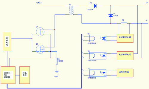
Figure 2 DC / DC converter circuit
It is mainly by the switching transformer, MOSFET power switch tube, rectifier components, sensor circuit (including voltage, current and temperature sampling), the subsidiary power source, UC3843PWM drive controller and related circuit. From the previous level in parallel input DC voltage added to the power switch MOSFET's drain, the gate input is controlled by the UC3843 chip set the frequency switching signal provided by the drive circuit. Step-up transformer through the switch, the rectifier filter to obtain the required DC voltage. UC3843 control chip is a current mode PWM control regulator. It has optimized DC / DC converters, low starting current, automatic feed-forward compensation, current limit, low-voltage lockout, pulse suppression, high current drive and up to 500kHz switching frequency and other characteristics. From the UC3843 internal circuit analysis, internal reference signal by the rectifier and transformer secondary voltage sampling value of the filtered error amplifier processes the error after the formation of voltage and sensing resistor voltage input to the PWM comparator, its output clock signals Trigger circuit for waveform processing, the final output frequency and clock frequency the same switching frequency signal.
Practical application in the discussion of issues related to
Switching power supply transmitters in the FM radio during use of some chance of failure, for many reasons. Transmitter Room of the environmental factors (such as ventilation, temperature and humidity), the power control cabinet mine problem, switching power supply design and the device itself is the problem, staff misuse problems are the cause of the failure risks. If you want to work equipment, in addition to master the necessary expertise, time and experience is necessary. Through the internal switching power supply fault protection circuit subsidiary of observation and analysis can often show the failure rate will be reduced to a minimum. The use of large capacity switching power supply energy storage capacitor, at work have a greater surge current, makes the switch close to the peak in the AC voltage when off. AC input transient voltage itself may lead to the same result. Therefore, the actual switching power supply circuit, often using a negative temperature characteristic thermistor connected in series in the block before the bridge rectifier. When the power switch is closed, the thermistor temperature is low, showed a high impedance state, surge currents are inhibited. With the current flow thermistor temperature, the resistance dropped to zero, the input voltage full load pressure to join. However, this basic protection mechanism for slightly less than in the actual use. If the power switch off again a few seconds to close, the thermistor is not sufficient time to cool, then close to the peak amplitude of the AC input voltage, will produce greater than normal inrush current, not only is this current sensing resistor in the voltage to generate higher than 6V, as LT1249 chip power-yet can not play a protective effect. This is leading to short-circuit power switch MOSFET breakdown of the direct cause of the damage. This is the beginning of strong wind and rain in Dalian disasters caused more than FM radio transmitter power failure was confirmed.
Varistor in parallel with the two ends of the same ac input power to absorb the surge. Change in ambient temperature conditions, the varistor resistance increases with the applied voltage decreases rapidly. Therefore, it has superior efficacy of surge absorption. In order to prevent the opening and closing due to surge voltage amplifier power supply, using pressure-sensitive resistor connected to the power line phases, which play the role of protecting power equipment.
Grounding line is the simplest most basic safety measures. Transmitter cabinet, amplifier box enclosure, power supply housings, panels and doors are connected, and connected to the transmitter's ground terminal, the transmitter installation is in place, should be the ground side of the machine (in the transmitter part of backplane) corners and the engine room to connect reliably to avoid leakage and mishaps. At the same time, also called the circuit ground of the grounding required to ensure
Conclusion
Although there are a variety of switching power supply topology combinations, due to the load type, power requirements, control methods on different occasions, there are different options, but the switching power supply control unit in the PFC and PWM control unit is the core, is the FM radio transmitter for high quality signal transmission with the launch of an important guarantee. In addition, the process of using the device, the work should be fully understanding of equipment and Gu Zhang Zhuang Tai phenomenon, Buduan to accumulate experience and lessons, which would help to grasp the failure characteristics of switching power supplies, Tigao FM transmitter Weihushuiping Guangbo ensure the equipment is in proper working condition .
Our other product:
Post Sky
seen
Post time 10/09/13
Enter email to get a surprise
Wholesale catalog
Wellcome to download list
1
字段
2
字段
3
字段
4
字段
5
字段
6
字段
7
字段
8
字段
9
字段
10
字段


