~The 10mW FM Transmitter~
-The First Stage-
This FM transmitter is the 1st Stage to the overall 3 stages 7 Watt FM Transmitter.
...updated as of October 30th, 2002
Getting Your Feet Wet
If you have never made a LPFM (low-powered frequency modulated) transmitter before, it would be wise to start with this project...to aquire the knowledge of just what is entailed in making your first FM unit..and to also get 'hands-on' experience. Even though the 10mW FM Transmitter would seem a very simple project as some would say, don't be fooled into thinking that everything will go 'right'. The word 'simple' in this project, only means that there are relatively few components in the overall project as compared to other LPFM units. The word 'simple' does not mean that the unit will work fine and dandy when you have completed it. It can still be very difficult to get the unit working right...or for that matter...at all..when you have finally soldered all of the components on the board and turned it on. Many variables come into play working in the vhf arena. The higher one goes in frequency, the more 'touchy' these units become. I have given a step-by-step procedure in making the 10mW unit. Utmost importance in this project is to stay true to every component...that is, substitution should not be allowed. I strongly suggest that you use each said component I have listed...and not stray from it. If you adhere to my precise way of making this unit, you chances of having it work in the end will definately be a lot higher. And if you keep patience close beside you...you will most likely see the unit perform at it's best! Once you have made the unit perform well and to your likings...you could then proceed to add the second stage...the 200mw unit and then later, the third, which is the 7 watt unit. I propose this wise decision in the fact that I have made all three...and starting from the first is a good thing!
If you are familiar with making these LPFM transmitters and have done well with them, you might want to just jump over the 10mW and start with the 200mW or the 7 watter...it is all up to you. But I would say, as one who has made these three transmitters...it would be very wise to start from the beginning (that is, starting with the 10mW unit), and then work your way up to the next transmitter...hands-on experience is by far the best teacher in the world!
So now, my friend, you have 3 choices of FM transmitters to choose from: The 10mW, the 200mW or the 7 Watt.
These three FM transmitters are all on this website. So without further ado, I surrender these fine FM transmitter projects for those who choose to venture out and make it.
...and let the project begin!
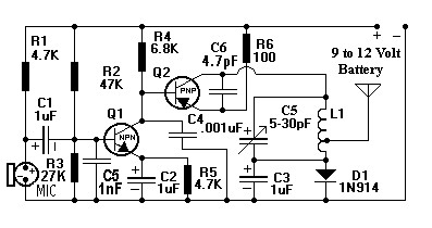
The Ten Milliwatt FM Transmitter
Let's begin...
This type PCB is the same style of design used on the 7 Watt FM Transmitter. Take a look at the digital snap shot on the 7 Watt webpage. Notice on that picture...all of the components that are soldered onto the copper...both the components and copper are on the same side of the PCB. I decided to use this style as it was very quick and easy to change out components...during the many months of experimentation. So, there are no holes to be drilled on the PCB, except for the four mounting holes. When looking at the 10mW PCB Template below, there are 12 copper island (shaded in orange) areas, which are surrounded by white areas. These white areas is where there is 'no copper'.That is the way you should make your PCB. I have had great results in using this style. Once you get it working, you may want to make another PCB...with holes...whatever you prefer. But my 'strong' suggestion is that you make the 'first' PCB according to my instructions. You will warrant a good show in the end!
Go ahead and print out a copy of the above PCB template. It has to be 91 mm's by 50mm's. If not, send the drawing to a graphics program and squeeze and/or stretch until proper measurements are acheived. Once this is done, you may continue to make your PCB the exact way it looks like in the said template. Let me say again...there are 12 copper islands (where you see the color orange) on the above template. Surrounding these islands are areas of no copper (where you see the color white). The above template should be mimicked as closely as possible in order to acheive my said style.
When you have completed and finished your new 'exact' PCB, drill a hole where the small black square is in the template. Then sip an 18 gauge solid copper wire through the hole and solder the wire to the frontside and backside of the PCB. Then cut off the excess. This will continue the ground plane (which is on the frontside of the PCB) needed on the backside of the PCB.
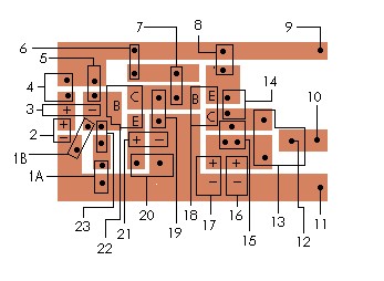
Once that is done...you may continue to start and solder all of your components on the PCB. All of the components are soldered in a vertical 'standing up' position, except for the two coils. To see where the components are positioned on the PCB, just look below...
Component Placement Guide
Just match up the number in 'Component Placement Guide' to the component in question in the 'Component Chart'.
Compartment Chart
| 1A - 5.6K 1/2 Watt Carbon Resistor
1B - .001uF Ceramic Capacitor
|
13 - Tapped Air-Core Coil |
| 2 - Electret Microphone |
14 - 4.7pF Ceramic Capacitor |
| 3 - 1uF Electrolytic Capacitor |
15 - 5-30 Variable Capacitor |
| 4 - 4.7K 1/2 Watt Carbon Resistor |
16 - 1N914 Diode |
| 5 - 47K 1/2 Watt Carbon Resistor |
17 - 1uF Electrolytic Capacitor |
| 6 - 1.2K 1/2 Watt Carbon Resistor |
18 - PNP 2N2907 or MPS2907 Transistor |
| 7 - 5.6K 1/2 Watt Carbon Resistor |
19 - .001uF Ceramic Capacitor |
| 8 - 100 Ohm 1/2 Watt Carbon Resistor |
20 - 4.7K 1/2 Watt Carbon Resistor |
| 9 - Positive lead to Power Supply |
21 - 1uF Electrolytic Capacitor |
| 10 - Antenna Terminal |
22 - NPN 2N3904 or MPS3904 Transistor |
| 11 - Negative lead to Power Supply |
23 - 22K 1/2 Watt Carbon Resistor |
| 12 - Tapped Leg on the Air Core Coil |
|
Accompanying Information on the Transmitter
L1 is a tapped air- core coil. Just click CLICK HERE to see how L1 is constructed.
If you are like me and have no test equipment, other than a homemade watt meter and a DVM, you can locate the main transmitting frequency by just using a typical AM/FM radio and switch it to FM...then go all the way to the lowest frequency...all the way to the left of the radio dial...which is around 87 Mhz...that is where I have adjusted the coils for. You will have to experiment with this as the transmitter will not only put out the main oscillating frequency, but also harmonics. If there were only one main transmitting signal coming from the frequency that you would like to transmit on... one would have no trouble in finding it...but with every main signal...there are harmonic signals on each side of the main. It can be very frustrating to capture that one 'main' signal. You might even think that you do have the main signal, when in reality, you are tuning in to some sort of spurious 'off the main' short range signal. I have talked to people concerning this, and they said that they also have found this out when trying to capture the main signal. So do remember this...whatever signal gives you the furtherest distance...that, my friend, would have to be the 'main' signal (and not some sort of off-shoot) of that specific frequency. Practice and patience will be your helping hands!
The Electret Microphone...Radio Shack sells this microphone as a two terminal connection and a three terminal connection. Use the two terminal connection. The side that is connected to the housing of the microphone is the negative side and that terminal goes to ground on the PCB. The other terminal is the positive side. Also, when you are at Radio Shack for this item and other items listed below, it would be wise to pick up about one foot of 75 ohm coax cable. With this cable you can 'extend' the length of the electret microphone so it won't be so close to the circuitry. I have mine right at 3 inches, which out and away from the circuitry and seems to work excellent as regards to clarity; not to mention your head staying a little ways away from the unit so as to not affect the frequency (see 'tank circuit' below).
2N3904 or MPS3904 Transistor...This transistor may be purchased at Radio Shack. Refer to the 'Component Placement Guide' for proper orientation of each leg of the transistor. Cut all the legs on the transistor to 1/4 of an inch before soldering.
2N2907 or MPS2907 PNP Transistor...This transistor may be purchased at Radio Shack. Refer to the 'Component Placement Guide' for proper orientation of each leg of the transistor. Cut all the legs on the transistor to 1/4 of an inch before soldering.
5-30pF Variable Capacitor...Radio Shack does not offer this component anymore. Mouser Electronics, here in the USA, does have them. Go to the 7 Watt FM Transmitter webpage to see Mouser's Toll Free Phone Number. This is one of two devices that make up the oscillating circuit (commonly known as the 'tank circuit'). A variable capacitor is needed in order to adjust for a specific transmitting frequency. It would be wise to understand how the tank circuit operates...since it is this variable capacitor, together with the air-core coil that you will experiment with...in order to capture the specific transmitting frequency you want. It will be left up to you to tune-in your transmitting signal to a receiver. Just CLICK HERE to understand how to tune your transmitter once you have made it and ready for the first 'turn-on'.
The 'tapped' Air-Core Coil...This is a home-made device and must be made by you. Just CLICK HERE for construction of the coil. This is one of two devices that make up the oscillating circuit (commonly known as the 'tank circuit'). A coil is needed in order to adjust for a specific transmitting frequency. It would be wise to understand how the tank circuit operates...since it is this 'Tapped' Air-Core Coil, together with the 5-30pF Variable Capacitor, that you will experiment with...in order to capture the specific transmitting frequency you want. It will be left up to you to tune-in your transmitting signal to a receiver. Just CLICK HERE to understand how to tune your transmitter once you have made it and ready for the first 'turn-on'.
1N914 Diode...This device may be purchased at Radio Shack. Observe polarities on diode. The cathode (that's the negative side of the diode) goes to ground.
4.7pF Fixed Disk Capacitor...This is a non-polarized capacitor, meaning that is does not matter which leg is used for placement. Just make sure one leg goes to the emitter of the MPS2907 and the other leg goes to the collector of the MPS2907. Keep the distance of the legs no further than 1/8 of an inch to the said transistor.
The 27K Resistor...This particular resistor will not be found at Radio Shack. Therefore, purchase a 5.6K and a 22K resistor and put them in series on the PCB. The ohmage will be close enough. I had notice no change in the audio by using this method.
The Antenna...I have used a four to five foot antenna on this unit and it radiated out well with it. You can purchase a four or five foot telescopic antenna from Radio Shack. Another choice can be two straightened-out coat hangers soldered together and then cut to 5 feet.
and finally...
Once you have finished making the unit, it is ready to be tuned to around 88 Mhz. That means this is the lowest end of the FM broadcast band. Find a portable FM receiver and tune it to around 88 MHz. Then position the FM receiver radio about 50 feet from the transmitter. Turn the volume to about half on the receiver. Then start adjusting your variable capacitor on the transmitter, while talking into it, to pick up your voice on your receiver. When you are familiar with tuning in to your specific frequency, and are satisfied with the way it sounds, get together with a friend and go out into the country or any wide open territory and see just how far the unit can transmit. You stay with the transmitter while talking in the microphone and have your friend gradually walk away from you while holding the receiver. Tell him to raise up his arm...when your voice can no longer be heard. Then you will have a clearer idea on just how far your unit will transmit. Remember to keep any kind of obsticles out of the 'line-of-sight' in relation to the transmitter and receiver. Do drop me a letter and let me know how things went. I wish you all the best. And so my friend...
...let the project begin!
Well, there you have it. Should you need questions answered or just concerned about a certain area in the project, do not hesitate to write me a letter.
Also, througout the project...do drop me a line. I would love to hear how things are going! I just might learn something new from you!
Our other product: