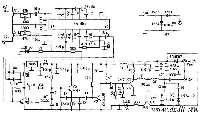
This article describes the stereo FM transmitter circuit shown in Figure 1. RF detector circuit as shown in Figure 2, the transmitter is simple, stable performance, making debugging easier, power, widely used and so on. Therefore, it is suitable for amateur electronics enthusiasts and the general and technical secondary schools, vocational high school students after-school electronic production. According to experiments, the +11 V DC voltage supply, the machine is transmitting power of about 2W; in the +14 V voltage supply, its transmit power up to 4W.
Work
The stereo FM transmitter mainly by the stereo frequency modulation, RF power amplifiers and RF power indicating circuit and other components. Machine stereo modulator with good performance, fewer external components, integrated FM stereo transmitter high ASIC BA1404 (consider the stability of firing frequency, the chip's internal frequency modulation and the RF amplifier section is not used). The stereo audio signal from potentiometer adjust the amplitude by the following, respectively, the RC network formed by the respective pre-emphasis circuits coupled to the first 1,18 BA1404 feet, left and right channels within the amplification by the BA1404, a balance adjustment processing section 12 after the pin output, with 13 feet of the 19kHz pilot signal output with the composite stereo signal component. The stereo composite signal composed by the V1 voltage amplifier,. Into the frequency modulation circuit frequency modulation, frequency modulation circuit composed by a V2. It is a very stable frequency improved capacitance three-point oscillator circuit. Oscillation frequency is mainly connected to the V2 base by the inductance, capacitance parameters. V3 etc. to promote the level of RF power amplifier. V3 collector external inductors, capacitors constitute resonant circuit, resonant frequency 88-108MHz. For maximum output power, V4 composed of high C RF power amplifier. Amplified RF power signal composed by the LC filter, matching network into the transmitting antenna in the air after the radiation. V5 instruction composed of RF power circuit, LED brightness to reflect the size of output power.
Component selection and production
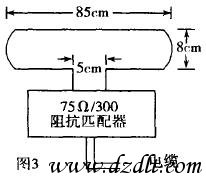
V1, V5 use low power NPN silicon transistor, such as 9014,9011 and so on. V2 use fT ≥ 500MHz high-frequency low-power tube, such as 9018,9016 and so on. V3 choose fT ≥ 500MHz, PCM ≥ 600mW high frequency in the power tube, such as BFR96, MRF571, 2SC2538, etc.. V4 choose fT ≥ 150MHz, PCM ≥ 10W high-frequency high-power tubes, such as 2SC1971. Detector diode detector with a high frequency diode, such as the 1N34, 2N60, etc., can also be high-frequency transistors be junction substitution. In addition to electrolytic capacitors and stereo modulation integrated circuit external capacitor polyester capacitor can be used, the remaining tiles are high frequency capacitor. In addition to the final stage inductor coil RF power amplifier circuit Xu Yong Φ0.8-1mm enameled wire wound on the 5mm rod, the rest are used Φ0.31-0.4mm enameled wire wound on a rod in Φ3.5mm. The turns are winning out in Figure 1. Antenna size and is connected with the impedance matching method shown in Figure 3.
Production and commissioning
As the work in the high-frequency state machine, therefore, in the installation, welding components for each component pin should be as short as possible. As the machine to work in a larger current must check all components and welding correct value only after the turn debugging. High requirements on the power machine, it is appropriate voltage 11-14V, 1.5A DC current greater than the regulated power supply (preferably batteries).
First debug launch frequency, first disconnect the final RF power amplifier coupled capacitor, and then power on, open the stereo FM radio, with plastic film to adjust the frequency modulation circuit inductance V2 base, avoiding the local FM radio station, make up the required frequency. Adjustment of RF power amplifier circuit simpler. Installed according to Figure 2, an RF power detector. In the RF output socket access a 50-75Ω/5W resistance, first RF power detector V3 collector, the collector inductance coil spacing adjustment V3, so that the maximum output voltage detector. Finally, the detector and the RF output socket of the radio frequency output voltage, adjust the RF output of each filter matching inductor coil spacing, so that the maximum output voltage detector, power can be the brightest light.
As the machine output power, after the machine commissioning, should be dedicated through the 50-75Ω coaxial cable to RF signals in an outdoor firing; Otherwise, the machine produces a strong addition to its radio signal interference caused by large hum, distortion, or silent, etc. failure, it will also enable closer working with CD, VCD machines stop working. The machine uses a very wide range, with the exception can be used to send stereo music, broadcast programs, can also transmit digital signals, or to launch remote alarm and so on.
Our other product:


