The 5 chip resistors used in this project are: 470R, 10k, 47k, 68k and 1M
RESISTOR AND CAPACITOR VALUES
5% TOLERANCE
The following refers to values with 5% tolerance:
With the size of resistors and capacitors getting smaller and smaller, the space for identifying the value is getting less and less.
To make things simple, a uniform numbering system has been adopted for both resistors and capacitors, consisting of three digits. The first two digits give the value of the capacitor in p or the value of resistance in ohms and the third digit is the multiplier.
This brings both capacitors and resistors into the same code and once you can read the code, you can identify everything.
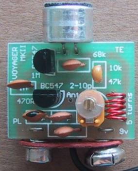
As an example, we will use a 47k resistor. See the third chip in the diagram above. The digits are 4 - 7 - 3. The digit "3" represents the number of zeros to put after the number "47." Thus we get 47,000 ohms.
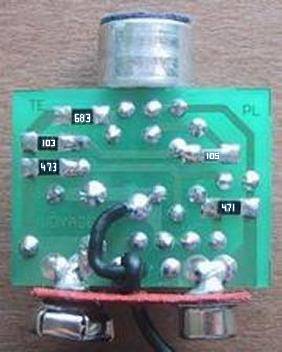
A 470 ohm resistor is "47" and one zero, thus we get 471 on a chip. A 10k is "10" and three zeros, thus 103 is written on the chip. A 68k is written "68" and three zeros, thus 683 is written on the chip and 1M is written "10" and five zeros. Thus the chip has 105 on it. These are the five values used in the Voyager Mk II.
A 10 ohm resistor is "10" and NO ZEROS, so the marking is 100. I know, I don't like it either but 150 on a chip is 15 ohms and not 150 ohms. 150 ohms is "151." Surface mount resistors start at 10 ohms and go to about 1M or 2M2.
A zero ohm resistor (used as a "bridge") is labelled "000."
It's only the range from 10 ohms to 100 ohms that will cause problems. When you see markings such as 120, 180, 470 etc it is best to check the resistance with a multimeter, to make sure the resistances are 12 ohms, 18 ohms and 47 ohms.
The tolerance for the above resistors is 5%.
1% TOLERANCE
Chip resistors are also available in a complete range of 1% values. Full details for reading these value can be found in our Basic Electronics Course.
If any 1% resistors are included in the kit for the Voyager, they will correspond to the values shown in the following diagram:
Keeping this in mind, we go to the markings for capacitors. The basic unit for surface mount capacitors is p (sounded `puff').
Very few surface mount capacitors are marked but those that have identification follow the p rule. This means 101 is 100p, and 102 is 1,000p. Another name for 1,000p is 1n (1 nano). 103 is 10n, 104 is 100n and 105 is 1u.
For those who have to convert from the old system, 1n is 0.001u, 10n is equal to 0.01u and 100n is 0.1u.
For surface mount capacitors, you must think in p. This will allow you to build any surface mount project in the future.
One point to note: With surface mount capacitors, the size of the chip is no indication of capacitance. The structure of the chip can be single layer or multilayer and this affects the size. Also the voltage rating of the capacitor affects the thickness of the dielectric and thus the size.
ASSEMBLY
Before you do anything, prepare the workbench for a completely different approach to work.
Lay out two sheets of clean white paper and place the kit of parts on one. Don't take the resistors out of the carriers until you are ready - a resistor dropped may be a resistor lost.
Study the board and note that all the components are identified by the printing on the top of the board, called the overlay or legend. You really don't need any instructions at all, but since this may be your first attempt at surface-mount, we will provide some helpful advice.
Note how the board stands on top of a 9v battery, with the battery snap soldered to the edge of the board. The positive and negative lands on the board are large so that the connections to the snap will be strong.
The microphone fits on the top of the board with two short wires and overhangs the board. Some microphones come with wires attached and this makes them easy to fit. Others may need to have wires attached and these can come from the leads of the capacitors.
The only 4 components that have to be fitted around the correct way are the two transistors, the microphone and battery snap. All the other parts, including the capacitors, coil and resistors can be soldered around either way. The air trimmer is best soldered so that the lead going to the screw is connected to the positive rail.
Once you have studied the photos, the PC board and components, you can start.
Here is the order for assembly:
5 surface mount resistors
6 capacitors
2 transistors
air trimmer (variable capacitor)
coil
battery snap, wire to hold the battery snap to PC board
microphone
(test the circuit with LED power meter)
antenna lead.
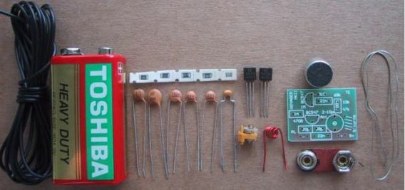
The Voyager MkII components
|
PARTS LIST
|
SEMICONDUCTORS
2 - BC547 or PN2222 (NPN transistors)
RESISTORS
(All are surface mount 1/10th watt)
1 - 470R marked as 471
1 - 10k " " 103
1 - 47k " " 473
1 - 68k " " 683
1 - 1M " " 105
CAPACITORS
1 - 10p ceramic-disc NPO type
1 - 39p ceramic-disc NPO type
1 - 1n ceramic-disc
2 - 22n ceramic-disc
1 - 100n monoblock
1 - 2p to 10p air trimmer
ADDITIONAL PARTS AND MATERIALS
1 - 5 turn coil .020in (0.5mm) enamelled wire 1/8in (3mm) dia
1 - electret microphone insert
1 - 9v battery snap
12in (30cm) fine solder
5ft 9in (175cm) hook-up wire.
1 - Voyager MkII PC Board |
SOLDERING
Now for the finer points:
The surface mount resistors required a fair degree of skill and you have to be good at soldering if you want to make the board look neat.
Read the notes on resistor identification and make sure you understand the 3 digit code.
Place the strip of resistors on the work-bench and take one out of the carrier strip, keeping the code numbers on top. Turn the resistor around so that the numbers make sense (make sure you don't read the numbers around the wrong way!) and place it on the board as shown in the diagram below, so that it is square with the sides of the board.
The SM resistors on the underside of the board
Standard soldering:
There are two ways of soldering the chip. One is to sit it in place and heat one end with a soldering iron while applying solder and then repeat with the other end.
The other method is called RE-FLOW.
Re-flow Soldering:
In this method you add a little solder to each land on the board and tin the ends of the chip while holding it in your fingers. Yes! you can actually hold the chip while soldering the other end. If you can't, you are taking too long.
When both the lands on the PC board and the ends of the chip are tinned, it is placed in position and held with a piece of wire such as an opened-out paper clip while touching one end with a soldering iron. This is repeated with the other end.
If you have added enough solder in the pre-tinning stage you will not have to add any more, otherwise a little solder can be added to make the connection neat and shiny.
It is important not to put any force on the chip during the soldering process as the ends can be easily detached from the ceramic substrate and the resistor will go open circuit. A hairline crack will be produced and the only way to check that the resistor has not been damaged is to measure it with a multimeter set to ohms range.
The other 4 chips are placed on the board in exactly the same way, making sure they are covering the lands and sitting flat on the board.
Double check the codes and if everything is correct you have carried out your first surface-mount placement!
The rest of the assembly is a lot easier. It's just a matter of doing things in the correct order.
All the other components are mounted on the top of the board and when two formats are combined like this, the assembly is called HYBRID.
Refer to the layout diagram for the placement of the 6 capacitors. These are soldered in place, one at a time. Some of the leads may have to be bent slightly to allow the component to fit down the holes as it is almost impossible to get all components in either .1" or .2" spacing.
Next, the two transistors are soldered in place. Push them down until they are 1/8" from the board as we want to keep the profile low. In addition, we have designed the circuit with the transistor leads as short as possible. If you place the transistors high off the board, the performance of the oscillator will be different to our prototype.
Solder the leads quickly so that you don't heat up the transistor too much.
The air trimmer is next. This must be soldered very quickly otherwise the plastic insulation between the plates will melt or buckle. Keep a finger on the trimmer to act as a heatsink and everything will be ok.
The coil is made from enamel coated wire and this coating must be scraped off with a knife or burnt off with a hot soldering iron so that the two ends are bright and shiny and tinned before fitting the coil to the board.
The kit comes with a pre-wound coil but if you are making it yourself, here are the details:
Wind 5 turns of 24B&S (.020in or 0.5mm) or 21B&S (.028in or 0.7mm) wire on a 1/8" (3mm) diameter shaft such as a small Philips screwdriver and space the turns as shown in the photo.
The coil determines the frequency of the oscillator and the turns will be stretched apart or squashed together after the project is complete. At this stage it does not matter about the spacing, as long as the ends fit neatly down the holes in the board.
Make sure the ends have been tinned by firstly scraping off the red enamel insulation with the back of a knife, then adding solder to the wire so that it covers the end of the wire fully and thinly. Push the coil up to the board and solder it in place with the turns evenly spaced.
Now the battery snap. If you want this project to produce the highest output power, the battery snap must be fitted directly to the board.
The project does not need an on/off switch as the battery is simply unclipped when not required.
To fit the battery snap, take it out of its plastic jacket and solder it directly to the edge of the board. The crown and cup on the snap will be loose when the plastic is removed and they will have to be tightened by tapping the rivet with a centre-punch. The "crown" terminal is soldered to the positive land on the board by fitting a piece of tinned copper wire through the two holes in the board. The ends are twisted together and fitted through the centre of the crown and cut short so that they don't interfere with the terminal on the battery.
Use plenty of solder as it is necessary to make a good mechanical connection as well as an electrical connection.
The terminals must not be able to be rotated and if they can be turned, they should be soldered again. Use very little solder inside the crown as the positive terminal of the battery must be able to fit inside to make a firm contact. Repeat with the other terminal.
One of the last components to fit is the microphone as its two leads are very fine and any unnecessary bending will cause them to break.
The microphone in the kit comes with two short wires attached and if you look at the solder-lands on the back of the device you will see one goes to the case. This is the negative terminal and must be soldered down the negative hole on the board.
Finally the antenna. This is soldered down the hole market "ant."
But before fitting the antenna you can check the output of the transmitter with a LED power meter. This is fitted to the antenna point on the board (without the antenna wire connected).
By using this piece of test equipment you can determine if the project is delivering an output. You will also need an FM radio to make sure the output is on the FM band.
THE LED POWER METER
The Voyager MkII connected to the LED Power Meter
The LED power Meter is a simple RF detector using diodes to charge a capacitor. The voltage developed across the capacitor is indicated by a multimeter set to a low voltage range. The circuit is soldered together without the need for a PC board, as can be seen in the diagram above and paper clips are used for the positive and negative terminals of the multimeter.
It will only take a few minutes to put this circuit together. The power from the output of the Voyager MkII is indicated by the illumination of a LED and the voltage reading on the multimeter gives a further indication of the output.
The reading is not calibrated and does not represent milliwatts output. It is only a visual indication.
|
LED Power Meter Parts
|
1 - 470R
1 - 100p ceramic
1 - 100n ceramic
2 - 1N 4148 diodes
1 - 5mm Red LED
1 - 2in (5cm) hook-up wire
2 - paper clips
No PC board required |
USING THE LED POWER METER
Connect the 2in (5cm) lead to the antenna point on the Voyager MkII board as shown above and turn the project on.
The lead of the LED Power Meter will act as an antenna, so place a radio nearby and tune it to about 88.5MHz or somewhere at the low end of the band. Move the turns of the 5 turn oscillator coil either together or stretch them apart until a feedback whistle is picked up by the radio. This is the frequency of transmission.
When the turns are pushed together the frequency decreases and when moved apart, the frequency increases.
You must not use any metal objects near the coil when moving the turns. If you do, the reading will be upset.
The best item to use is a match or plastic knitting needle as you should keep your fingers and hands away from the coil while adjusting it.
The multimeter will show a reading of about 2v and this voltage will depend on the quality of the transistors. Once you are satisfied the project is working, remove the LED Power Meter and solder the antenna lead to the board.
Move the radio a short distance away and tune across the band to make sure the output is coming through and to see if you have picked up the main frequency of transmission.
Carry out some experiments yourself and you will be very impressed with the performance.
By moving the Voyager MkII further away you will be able to pick up the sounds it detects. Make sure the frequency of transmission is well away from any radio stations as the signal from a station will swamp the Voyager MkII when you are testing it for range. You can do this by adjusting the air trimmer. You can see the vanes moving in and out of mesh with the stators and the meshing should be mid-way at the start of the test so you can raise or lower the frequency by turning the trimmer.
As the vanes move out of mesh, the capacitance of the trimmer decreases and the frequency of the output increases. When adjusting the trimmer you must use a non-metallic instrument. The best is a plastic knitting needle filed to make it into a flat screwdriver.
If you do not get a squeal from the radio you can assume the frequency is lower than the band (we have designed the output to be very close to the bottom of the band) and it may be just a little too low.
In this case you will have to raise the frequency by expanding the turns of the coil. This will bring the output onto the FM band and you can shift it slightly up or down with the air trimmer to get it away from other stations.
To get the maximum range the antenna should be stretched out straight and placed either horizontally or vertically. The receiving antenna must be in the same plane to get the maximum range and both antennas should be as high as possible.
The signal is generally not affected by brick walls, glass or plaster but it will not pass through metal of any kind such as aluminium foil or metal cladding. Trees can also have an effect due to the amount of moisture they contain.
The signal will also find it difficult to get out of a car and you must place the antenna near a window but away from the metal frame-work as this will almost totally absorb the signal. The range from a car will be a lot less than the 800m we stated at the beginning.
IF IT DOESN'T WORK
If you cannot detect an output on the LED Power Meter, you can safely assume the oscillator stage is not working.
Measure the current for the project. It should be about 7mA. If it is only about 3mA, the oscillator transistor may be damaged or not being turned on.
You cannot measure any of the voltages around the oscillator transistor and expect to get an accurate reading as the leads of a multimeter will upset the operation of the circuit.
However if you measure the voltage on the emitter of the second transistor and find it is zero, it is not being turned on and you should check the 47k base-bias resistor. If it is 9v, the transistor may be shorted or the 470R resistor may be open circuit.
But the most likely cause of the project not working will be a soldering fault, such as a bridge between two tracks, poorly soldered joints, or two components that have been swapped - such as the 47k and 470R.
The best thing to do is give the project to someone else to check as it is very difficult to check your own work.
If you have used your own parts to build the project, the fault could be in the markings on the components (or incorrect reading of the values) or the wrong size coil. The only solution is to buy a kit and put it together - you can then compare one project against the other.
If you are picking up a blank spot (called the carrier) on the dial but no audio, the fault will lie in the first stage or the microphone.
Check the voltage on the collector of the audio transistor. It should be about 2.4v, however if it is above 6v or less than 1v, the transistor will not be biased correctly and the 1M base-bias resistor may be at fault.
The electret microphone needs only about 50mV across it to work and the only real way to check it and the audio stage is to use a CRO or audio amplifier (our prototype had 200mV DC across the microphone). By whistling into the microphone at a distance of about one foot (30cm), you will get an output of about 10 - 30mV. The audio transistor will provide a gain of about 70 and produce an output of about 700mV - 2,100mV, as mentioned previously.
If the microphone does not produce at least 10mV, it may be around the wrong way, damaged, or have very low sensitivity. Reducing the 68k load resistor may help if the microphone is a low sensitivity type.
FITTING THE BATTERY
The Voyager MkII is designed to fit on top of a 9v battery and doesn't need any case or potting. The safest thing is not to enclose it at all as heatshrinking can squash the coil and change the frequency of operation.
Fully-assembled devices SB-800 are available from Talking Electronics, for those who are not good at soldering or want a built-up unit.
They are covered with heat-shrink so they can be handled and easily fitted to a battery. You can heatshrink your own model by buying a short length of heat-shrink tubing and placing it over the board and shrinking with a candle or gas torch. Crimp the ends with a pair of pointed-nose pliers so they stick together and make a good seal. Cut around the two battery terminals and make a smaller hole for the air trimmer so the frequency can be adjusted, and the project is ready for use.
That's the complete story. I hope you get as much fun out of the Voyager MkII as we did in designing it.
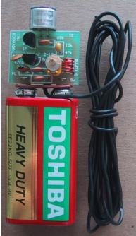
Voyager MkII fitted to a 9v battery with 1.75m (6ft) antenna
LOCATING A TRANSMITTER
If you are trying to find a transmitter such as the Voyager MkII, when it is transmitting, you can turn on a transistor radio and tune across the dial. You will get a feedback whistle (when you are in close proximity) and this will indicate a transmitter is present.
But the job of actually locating the transmitter with a radio is very difficult.
A radio has no directional ability and it will need two people to do the searching. One will need to hold and listen to the radio while the other searches through the room looking for the bug.
If the searcher makes very low level sounds, the person with the radio will be able to detect when the searcher is getting close to the microphone. The problem with this is most transmitters are so sensitive that it is difficult to know when the searcher is getting really close to the microphone.
Two employees of Talking Electronics tried for 15 minutes to find a hidden bug with this method and failed to locate it, so the chances of tracking it down are slim.
The other method is to use a Bug Detector. Talking Electronics has designed a very simple-to-operate device called Bug Detector 2000.
It is extremely easy to use and only needs to be switched on with the antenna extended and the volume turned up.
It is a broad-band receiver and picks up the whole FM band at the one time so you don't have to tune across any of the frequencies.
This means you can't miss anything and by simply moving around the room with the antenna outstretched like a probe you will get a feedback whistle from the built-in speaker, if a transmitter is present.
By turning the volume down, the meter on the front of Bug Detector 2000 will come into operation and register field strength.
It's simply a matter of moving around the room again, this time observing the deflection of the needle on the meter.
The needle will fully deflect at a distance of about 3 metres (10ft) from most transmitters and to get closer you must make Bug Detector 2000 less sensitive by reducing the length of the telescopic antenna. This will allow you to "home-in" and get right up to the bug, which may be hidden under a book or shelf.
Using the radio method described above will get you close to the transmitter but then you will have to do a lot of tapping around to try and find the bug itself.
Bug Detector 2000 achieves a result almost silently so that once the bug is located, it can be left in place or removed, according to the circumstances.
 Enlarged overlay and the trackwork for the Voyager MkII circuit board


