FM stereo transmitter
The cell area we are referring to here refers to a radius of 1-3 kilometers. Such an FM transceiver system is more suitable for campus or unit broadcasting. This article will elaborate on the cell frequency modulation (stereo) transmitter device made by using the miniature and efficient wireless sound transmission module MEC002A produced by Minshi Technology
The MEC002A miniature high-efficiency wireless sound transmission module developed by Minshi Technology has the advantages of small size, large RF output power, high sound induction sensitivity, and relatively stable output frequency. The FM transmitter circuit constructed by it has a simple structure, easy to manufacture and debug Convenient, only need to add a radio frequency power amplifier circuit composed of C1971 to realize the frequency modulation transmitting circuit within three kilometers. The circuit structure is quite simple, so it is more suitable for amateur radio enthusiasts.
Figure 1 is a three-kilometer mono FM transmitter circuit composed of MEC002A. It can be seen that the radio frequency circuit actually has only two stages. One level is a radio frequency oscillation output circuit composed of MEC002A and peripheral related frequency control devices, and the other level It is a Class C RF power amplifier composed of C1971 and related components. The other components are mainly used for power supply, filtering and microphone amplification. Although MEC002A contains a microphone amplifier circuit, for some units, an extra microphone is needed instead of the high-sensitivity microphone amplifier circuit in the module. In order to obtain a stable operating frequency, this circuit is equipped with a multi-level power supply regulator and filter. In the circuit, U1 (7812) provides a stable 12V voltage for the MEC002A module, and C12-C15 are power supply filter capacitors to make the working voltage more stable to ensure that the MEC002A module will not produce frequency drift due to changes in the working voltage. R3, R7 and L3 are inter-stage decoupling devices, which can effectively overcome the mutual interference caused by the use of the same power supply between all stages. Q1 and its peripheral components constitute a microphone amplifier circuit. The audio output is coupled to W1 through C5 to control the volume of the microphone. The controlled microphone volume is coupled to the modulation terminal (pin 7) of MEC002A through C8, which is a good match for the internal high-frequency oscillation circuit of MEC002A. Perform frequency modulation. The 6th pin of MEC002A is its internal microphone audio amplifier output pin. After W2 controls its sound sensing sensitivity, it is coupled to pin 7 from C9 and also modulates the MEC002A's internal high-frequency oscillator circuit. If you want the MEC002A's internal microphone to not work, only Just leave pin 4 in the air. When you need to start the internal microphone circuit, connect pin 4 to ground. CV1 is the RF output frequency control capacitor of MEC002A. By changing the capacitance of this capacitor, the output frequency of MEC002A can be changed in the range of 68-118MHz. It basically covers the entire campus radio and FM radio frequency bands. However, once the output frequency changes, the RF power amplifier of the next stage must be adjusted accordingly to maximize the RF output power and the farthest transmission distance. Therefore, it is recommended to specify the required operating frequency when purchasing, so that the manufacturer can adjust the gain of the power amplifier circuit to the maximum at the predetermined frequency. The third pin of MEC002A is the RF output pin. The modulated FM wave is output from this pin and sent to the base of the Class C amplifier composed of Q2 (C1971) through the frequency selection network composed of C16, CV2, and L1, MEC002A Pin 1 is the power supply terminal, and pin 5 is the power ground. Q2 works in Class C state, and the bias resistor provides a negative bias voltage for its base, which can make the output efficiency of the circuit higher than Class A. The prerequisite is that the previous stage must have sufficient excitation power to work at 12V. For MEC002A under voltage, its output power is nearly 200mW, which can fully drive the Class C amplifier circuit. U1 provides a stable 15V working voltage for C1971. L5, L6, CV3, CV4 form a frequency selection network. By adjusting CV3 and CV4, the output power of Q2 can be effectively transmitted to the transmitting antenna. The working current of the whole machine is about It is 800mA, and the RF output power is about 3W. This circuit also provides the city power supply function. D1-D4 form a full-bridge rectifier circuit, and C30-C33 are filter capacitors, which can reduce the AC ripple caused by the city power. The input AC voltage is controlled at about 18V. The working DC voltage of the whole machine is 18V. When using the voltage of 13.5-18V, U2 can be dispensed with. Just use a jumper to short-circuit its 1 and 3 pins.
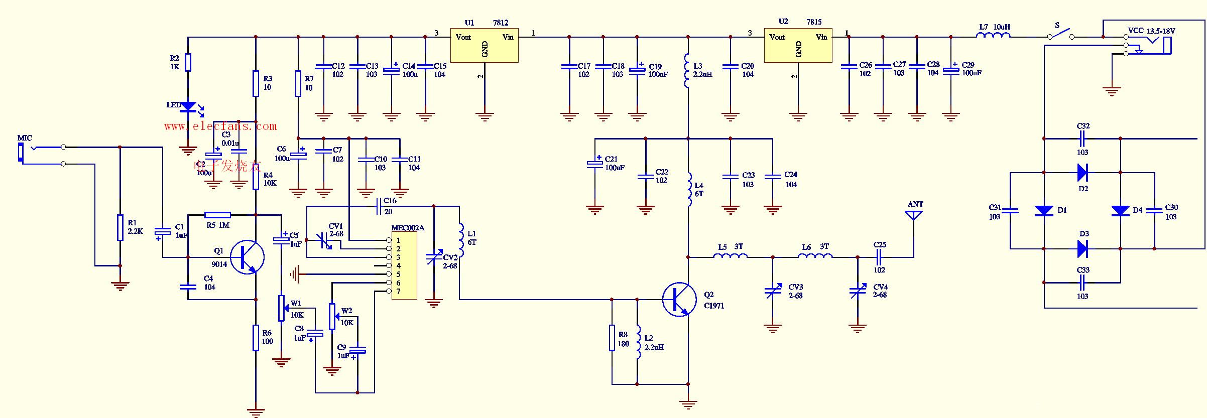
FM stereo transmitter, click on the figure above to enlarge the circuit diagram.
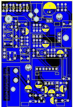
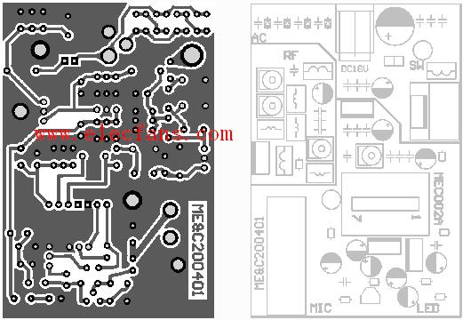
Figure 2 is the assembly diagram of the whole machine, Figure 3 is the circuit and solder layer circuit board diagram, Figure 4 is the component assembly diagram, and Figure 10 is the physical assembly diagram
For community broadcasting, the current mono broadcasting can no longer meet the needs of music lovers, and more listeners hope to receive high-quality FM stereo broadcasting. Figure 6 adds a level of FM stereo encoding circuit composed of BA1404 on the basis of Figure 1, so that the transmission sound quality of the circuit is further improved, and it can transmit FM stereo signals. BA1404 is a FM stereo modulation transmitter integrated circuit. Here we discard its high-frequency oscillation part and use it directly to modulate the MEC002A FM oscillator circuit with the 19KHz pilot signal output from its 13 pin and the audio signal output from its 14 pin. . The components connected to pins 1 and 18 form an FM pre-emphasis network. With the receiver's FM de-emphasis network, the ideal frequency response can be effectively obtained and the received sound quality is the best. In addition to providing power indication, LED also provides stable operating voltage for BA1404. The two transmitter boards also reserve the wiring pads for the microphone volume control potentiometer and the power switch. Users can modify them according to the schematic diagram, and add the power switch and the microphone volume control potentiometer.
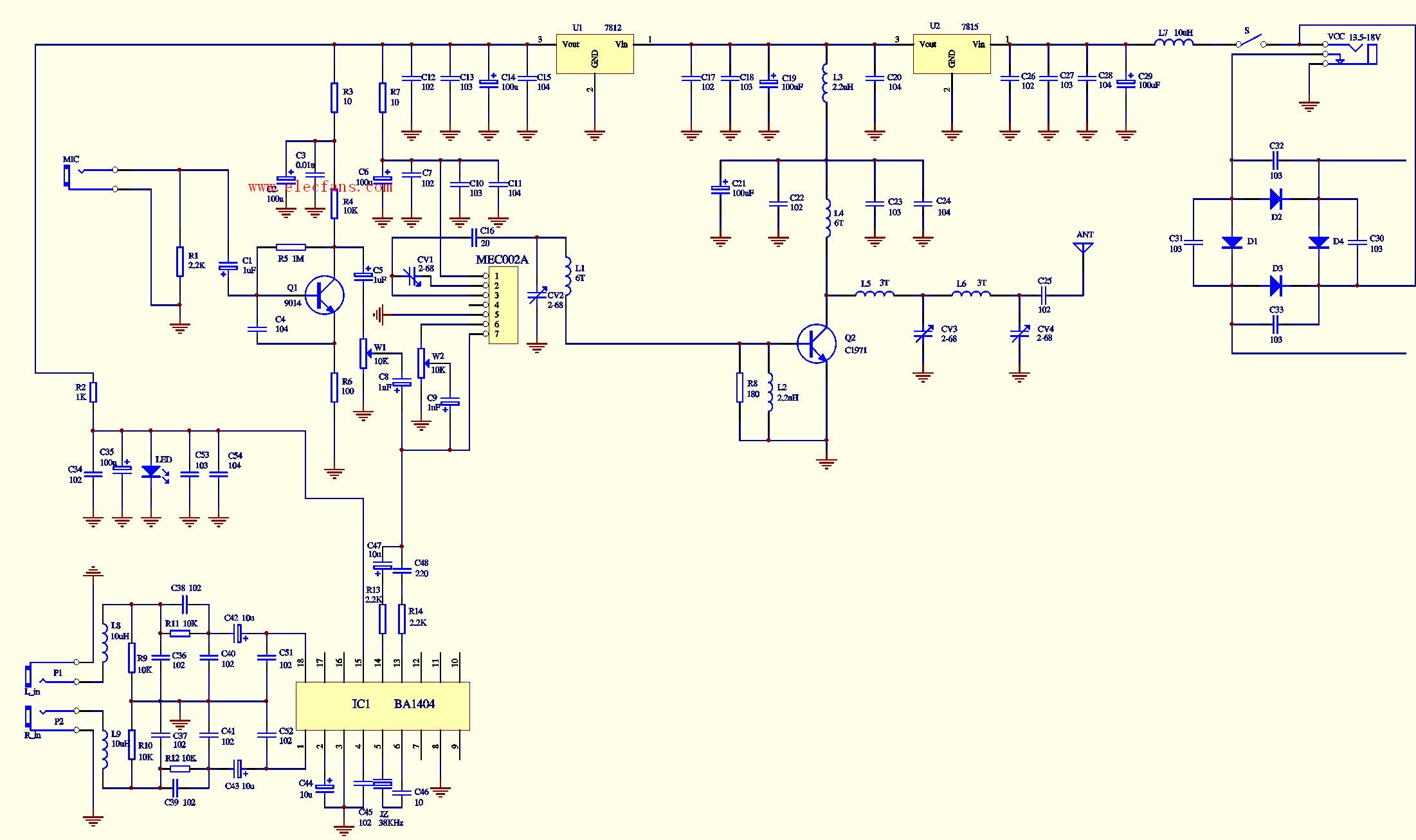
Figure 7 is a complete assembly drawing of the FM stereo three-kilometer board, Figure 8 is a circuit board drawing of the solder layer of the circuit, Figure 9 is a component assembly drawing, and Figure 10 is a physical assembly drawing.
Precautions for use: (1) Sound source and antenna: Because the transmitting power of this unit is slightly larger, the field strength it generates is enough to affect the normal operation of the surrounding electrical appliances with poor shielding. It is recommended to transmit the above two types during use. The board is shielded with a metal box, and the antenna is led outdoors or far away from the sound source. In the actual test of this circuit board, the whip antenna is directly locked on the circuit board for transmission. When the MP3 player is used as the sound source, it is close to the transmitter and the MP3 player is not disturbed, but it is close when using the Walkman or VCD player as the sound source. The transmitter board will not work normally within three meters, and other audio sources have not been tested; however, the above phenomenon will not occur when using an outdoor antenna to transmit. In addition, the use of a computer as a sound source should also be far away from the transmitter, especially for stereo transmitter boards, which may cause noise. The outdoor antenna is best to use the GP antenna introduced on the Minshi website or the "half-wave dipole" antenna made by the horn antenna, and use a 50-ohm coaxial cable to transmit radio frequency signals. The use of a 1.5-meter whip antenna will greatly increase the transmission distance of the 1-meter whip antenna matched with the original board. (2) Power supply: Due to the large operating current of the launching board, the requirements for power supply are high. The output current of the power supply is required to be no less than 800 mA at 18V. Therefore, the power supply with too small output power will make the launching board not work properly. For example, using two 9V stacked batteries in series, the battery will be exhausted in a very short time. When using a DC adapter to supply power, the output current is required to be greater than 800 mA, and the working voltage must be selected at 13.5-18V. The test power supply we use is made of TL431 precision voltage reference IC. (3) About the solution of temperature drift: The three-kilometer board will produce a small range of frequency drift with the increase of working temperature in the first few minutes of starting up, and finally stabilize at a working frequency. The more effective solutions are: A . Replace the CV2 and CV4 adjustable capacitors in the circuit with fixed ceramic capacitors (high-frequency capacitors with black dots) with a capacity in the range of 20-68P. (Note: The change of the value of CV2 has an impact on the transmission frequency) B. Fix the heat sink to the metal casing, increase the heat dissipation area, so that the heat can be dissipated as soon as possible, and if possible, install a small fan for the heat sink. The above two suggestions can effectively overcome the frequency drift caused by the temperature of the three-kilometer board.
Our other product:


