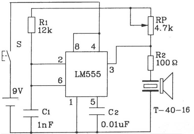
The simplest wireless transmitter circuit diagram (1): Ultrasonic transmitter circuit composed of 555
The 40kHz oscillating pulse output from pin 3 of the 555 drives T-40-16 to work, making it emit a 40kHz ultrasonic signal. The working voltage of the circuit is 9V, the working current is 40~45mA, and the control distance is greater than 8m.
The simplest wireless transmitting circuit diagram (2): Ultrasonic transmitting circuit composed of discrete components
The ultrasonic transmitter circuit T/R-40-16 composed of discrete components can transmit a string of 40kHz ultrasonic signals. The working voltage of this circuit is 9V, the working current is 25mA, and the control distance can reach 8m.
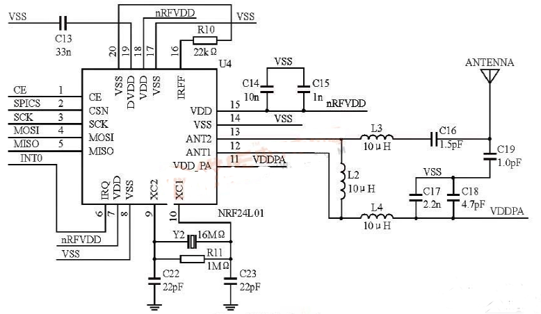
The simplest wireless transmitter circuit diagram (3): The schematic diagram of the radio frequency transceiver circuit based on nRF24L01
nRF24L01 can work in the 2.4GHz~2.5GHzISM frequency band. The transceiver has built-in functional modules such as frequency synthesizer, power amplifier, crystal oscillator, and modulator. It is a highly integrated wireless transceiver. The external circuit of nRF24L01 is relatively simple and incorporates enhanced ShockBurst technology, where the output power and communication channels can be configured through programs. At the same time, the power consumption of the chip is extremely low. When transmitting at a power of -6dBm, its working current is only 9mA; and when receiving, its working current is only 12.3mA. The control circuit of nRF24L01 can be connected with the SPI port and GPIO port of the STM32 controller. Figure 1 shows the schematic diagram of the RF transceiver circuit composed of the chip.
The simplest wireless transmitting circuit diagram (4): FM wireless transmitting circuit diagram
As shown in the figure is an FM wireless transmitter circuit composed of 555 audio oscillator and FM transmitter circuit. This circuit can be used in small transmitter circuits.
FM wireless transmitting circuit
In the figure, the audio oscillator is composed of 555 and R1, R2, RP1, C9, etc., and its oscillation frequency is

The frequency can be adjusted to the required frequency value by adjusting RP1. VT1 and L2, C3, C4, etc. form a capacitor three-point high-frequency oscillator, the oscillation frequency is 80 ~ 108MHz. The audio signal output by 555 modulates the triode oscillator, and the modulated wave signal is transmitted to the air through the whip antenna. The FM transmitter circuit is composed of 7809 and so on. The 7809 is a high-precision AD acquisition chip. It uses a 5V single power supply and contains 16-bit successive approximation registers, with high sampling accuracy and low power consumption. The FM transmitter circuit can also use a cheap low-frequency power tube 9018, with a transmission power of up to 120mW and an operating distance of up to 1km.
The simplest wireles
s transmitter circuit diagram (5)
The function of the wireless signal transmitter is to send the stimulation parameters set by the PC machine to the "backpack micro stimulator" in the form of wireless signals. It consists of the following parts: a wireless signal transmitter (Transmitter), a step-down voltage regulator circuit composed of AMSl117—3.3, an Atmega8L microprocessor, a level conversion circuit between the PC serial port and the single-chip serial port. The connection relation of each part of the circuit of the wireless signal transmitter is shown in Figure 3. Based on the CCllOO wireless transceiver ccllOOA-01 (Liqi International Trade Co., Ltd.) is a low-cost, low-power ultra-high frequency (UHF) transceiver, the module is small in size (20mm&TImes;30mm&TImes;6mm) and light in weight (2.3g), the transmission distance is greater than 200m, and it mainly works in ISM and SRD frequency bands.
Circuit connection diagram of wir
less signal
transmitter
Because the logic O of the RS232 serial port is defined as between 5 and 15V, the logic 1 is defined as between 1-5 and 15V. And the one-chip computer can only receive TTL level (input high level "2.4V, input low level "0.8V, noise tolerance is 0.4V). Therefore, it is not possible to communicate directly between the PC and the single-chip computer through the serial port line, and must undergo level conversion. Here, the product produced by MAXIM is selected. RS232 interface chip MAX3232, it uses a single power supply voltage to supply power, and the power supply voltage can work normally within the range of 3.0 to 5.5V. The system uses a 9-pin serial port, and completes communication through 3 wires: RXD, TXD and GND, corresponding to line 2, 3 and 5 on the 9-pin serial port. In the system design, the chip MAX323 uses 5.0V voltage power supply, and the single-chip microcomputer uses 3.3V voltage power supply. Therefore, the 3.3V voltage regulator chip AMSlll7—3.3 is selected, and the entire launch pad can be powered from the PC through the USB interface
Our other product:


