Almost every electronic enthusiasts are using radio ambitions, regardless of an aircraft or remote communication with the outside world, all expressed their hope that the signal emitted presented to you here a pocket transmitter, great for beginners, simple circuit system, low cost, power output of not more than 5-8mW, the range of housing areas can be fired from 100 meters, with an ordinary FM radio receiver, showing a sensitivity and clarity is superb, the circuit design of the most challenging Just some of that half-wave antenna 3V power and have such a launch capability. In addition, because the circuit requires very few parts, so it could be placed in a matchbox (than domestic - as matchbox large number of) years, as the device is indeed God, without our noticing, but not limited to this purpose on, it could be placed in the baby room, gates or corridors, monitor the actual situation, in addition also the night when a security device. Circuit current consumption less than 5mA, with two batteries can work for between 80 to 100 hours.
Circuit is very stable under normal operation, frequency drift small, test: work 8 hours later, still no need for further school receiver. The only affect the output frequency is the status of the battery when the battery ages, the frequency changes slightly.
To take this production, learn about the FM transmitter, can understand its advantages, especially where it produces very high quality noise-free signal, even if the use of low power to send, and very easy to achieve good range.
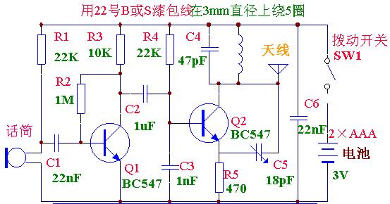
Points in the circuit can be seen from Figure 2, an audio amplifier and an RF oscillator.
Electret microphone in the actual possession of a FET, if you like it, can be regarded as a, FET before the diaphragm of the microphone capacitance change zoom, this is a very sensitive microphone in a very off the reasons.
Audio amplification is by its emitter tube Q1 off as crystal, gain about 20 to 50, the amplified oscillation signal sent to the base level.
Q2-level work in some oscillation frequency of 88MHz, this frequency from the oscillation coil (5 laps) and the 47pF capacitor adjustment, the frequency determined by the transistor, 18pF capacitor and a minority of transfusion bias components, such as 470Ω emitter resistor and 22K base resistance.
Power on time, 1nF base capacitor charge gradually through 22K resistor, and 18pF is the 470Ω resistor by the oscillation coil charge, but more rapid, 47pF capacitance charge (although one end is only a small voltage), the coil magnetic field .
Gradually increase the base voltage, the transistor, and effectively on both sides of the internal resistance and connected to the 18pF. When the 1nF capacitor charged to voltage of the pole occurs when the frequency of several messy, therefore, we assume that the discussion near the voltage at the time.
Base voltage continues to rise, 18nF capacitor with pressure trying to stop the movement of the emitter to the capacitor energy depletion and do not stop moving when the shot level, the base emitter voltage of a lower transistor is off, the coil current flow stopped, collapse field decline.
Magnetic field decline collapse, resulting in the opposite direction of the voltage, collector voltage, in turn from the original rose to more than 2.9V. 3V, and 47pF capacitor in the opposite direction, this voltage is also affected on the 18pF capacitor, and 470Ω emitter resistor voltage drop on the tube so that grain break into the deeper end. 18pF capacitor charging, the voltage drop shot, and fell off of a crystal tube began conduction, current flows to the coil, the magnetic field confrontation with the decline of collapse. Coil voltage reversal, the formation of collector voltage drop, the change in transmission through the 18pF capacitor to the emitter, the results of crystal off tube into a deeper turn, the 18pF capacitor circuit, began to repeat the cycle again. Therefore, Q2 in the form of a vibration, resulting in the exchange of 88MHz signal. Amplification of the audio signal into collapse by the 0.1uF capacitor! Q2 of the base and change the oscillation frequency, produce the desired FM signal.
Production process
Installed before the system is best to pre-prepared printing plates and two empty cells released fire pear boxes, in the end to see how much space is available. Although space is limited, but still leave a little space for a single row of the matches, these matches can glue a piece of paper posted on the cards aimed to cover the circuit, giving the impression that it is but a box of matches, not aware that a device.
Now all the parts on the work table, one by one part to distinguish their values, and then classified in order of precedence is good, this paradox in a very methodical, to avoid welding the wrong parts. Tin-line of the best in fine 0.6lmm with special resin (rosin) solder wire, because of its small body, welded to quickly and easily on the tin, 15 to 20w with a small electric iron sufficient, iron before use with a sponge to wipe Tsui clean, to be made is the only coil, needed a 22 BS (Ф0.5mm) or 24 BS (Фm.71mm) of the enamelled copper wire or package tin copper wire. 3mm diameter of the coil in the 5 laps around the shelves, such as medium-sized screwdriver can last around, and then circle and the circle of 5.5mm separation between the left and right. Adjust the frequency of the last time we will be winding through the stretch before and after the compression or change the output frequency. If your coil of magnet wire to do so, to the line of patent leather on the ends stripped, and then a bit of tin. Now according to Figure (3) direct placement position welding of chassis parts, starting with resistance began, followed by capacitors, transistors, coils, and then Jane, resistance upright on the floor, but maintain a high level to a minimum. Crystal Hugh tube due into bottom pin, and even control the height is not prominent.
Welding together two batteries using switches, and then use the cable connected to electrical ground to the floor on poles. Finally, a 10cm-long copper wire connected to the bottom of the "A" point, as the antenna, even if the entire manufacturing process is completed.
Why?
Do you wonder why the circuit does not work? How many times have found that after installed the circuit does not work? Please do not blame themselves, or again that the religion of your magazine shouted abuse, often because of the so-called "error" caused. All factory manufactured parts has its value, but this value only by the "balance" within, rather than printed on it "normal" value. This difference is called degree of error, if error is 5%. This means that the actual value of the parts will be under its marked value of more than 5% and 5% in any one place. Error is often used in resistors, capacitors, transistors and other components such as microphone, coil and integrated circuits.
However, there is another factor, called the boundaries of each component in the circuit, the occasion has a range of values allowed, as long as the value is still within the scope of, or within these limits, circuits appropriate work, choose the time of each component - like in the middle of this range. Most of the circuit is not strictly limited, such as selecting another component from the specified higher or lower value, generally worked well, if not a circuit is not very strict restrictions on the selected value is very appropriate. When you publish a line through the magazine out, they will have a variety of different sectors of the trial, to obtain a required parts from various sources. Sometimes they use the designated value, and sometimes they choose plays a number. Also, some parts are 1-5% error, while the other indicated value of up to 60%, when the difference between these parameters and boundaries in any way under the mix, you run into the circuit does not work is very common.
Taking the microphone, for example, in the 3V power supply, some would simply just use the 100K load resistor (R1) have a very good sensitivity, the other may take up to 4.7K can achieve acceptable sensitivity only from the appearance you can not tell the difference, they seem the same, but the difference was on the electrical characteristics is far. Similarly, the body can also be applied to the transistor, specification sheets may note two features near the same, but, when they take: the circuit, meaning a work that, while the failure of another work. Do not worry about that but I am afraid the above paragraph fails, as long as the circuit components carefully considered the requirements to do step by step, is completely successful.
Circuit tuning
After all parts are welded, best to view with the naked eye all the welding points, welding Shipi, some did, Huozhe solder used too much Erzao Cheng and Lin Jin short, a thorough investigation to clear before taking the calibration and test performance, test steps yes plus a short antenna (5 to 10cm long) in the bottom of the A point of tuning - FM radio in the band department, the search for the signal. Best to make the transmitter and radio to maintain a certain distance, to prevent the prosecution of any harmonics or side of the waves pick up. If not check the radio to the carrier, said the frequency may be too low, the oscillation coil slightly elongated, and try again. If you use package tin copper wire wound coils, attention should be between the map and circle each encounter. Such as the use of patent leather copper, the need to know the circle of connectivity can be used multimeter to measure the low block it, or measure the circuit current should be about 4-6mA. Once the check to the carrier, the device placed in one side near the clock to check the sensitivity of the circuit, the radio must send a clear and powerful "tick, tock" sound, the circuit should be more sensitive than your ears. Microphone of the load resistor (R1) determine the sensitivity, it could be reduced to 10K, or raised to 47K, depending on the sensitivity of demand may be.
To determine the frequency of firing completely away from any FM radio Tuen your local station, because the radio signals issued a powerful, when you test distance, will cover the device. The coil compression, the frequency will be reduced; to the stretch, the frequency will increase, so avoid use fine-tuning capacitor, saving the cost of this machine, but can also be used if you like fine-tuning capacitor. By the way, C4 is best to use a 39pF ceramic capacitors, the other 10pF or 22pF tuning capacitor, and in total, so that the circuit can be adjusted more carefully. Coils can easily deviate from the FM band to adjust.
In theory, with the sensor should be adjusted to maintain the tuned circuit L / C ratio, but we need a very small range, so there is no limit. Instructions regulating the use of a table with FM receiver can determine the output power of the machine number, which is in need of a comparison, the four units of instruction form instructions degrees, that is very good output, in testing the machine with 10cm long antenna for horizontal display, from the tuner degrees to 10 meters. Degree subject to four units, namely, that with a half-wave antenna. (170cm long), the function to launch about 300 meters away.
If not how to do the work?
In the FM receiver can not receive the emitted to the carrier, first of all be assumed below normal 88-108MHz FM frequency band, this is the most likely cause.
The current measurement circuit, if 4-6mA, said circuit is at work, slightly lengthening the coil, and scan the whole band, when exposed to any component floor, only with a non-metallic screwdriver, and leave the battery because your skin caused by hand capacitance effects will lead to significantly offset the circuit, and may completely stop output. Also, the maintenance of 3V power supply is also important, and to the battery close to the floor.
The wiring must be shown in Figure (3), the maintenance of the same circuit distributed capacitance, the circuit once the work in order to change their order, but in the first test step, each component must be adhered to in full as the figure placed.
Oscillator working at about 88MHz, unless you have a 100MHz oscilloscope, otherwise it is difficult to see the waveform, or antenna directly connected to the 75Ω input frequency meter.
If not the above test instruments, needed multimeter for DC voltage measurement, see Oscillation Tube Q2 have the correct value of pressure.
Measure the base voltage and emitter voltage, a common multimeter on the circuit because of its role, will direct the two is about 2V, only the high impedance meter, such as the FET voltage meter, it instructed the emitter and base are 2V There 2.5V. (Recommended number table) if this voltage there are two test points, work on the assumption that the transistor, but it may launch an error frequency. 18pF output capacitor back to tie in with BC547 transistor, such as the intention to use another number can be reduced to 10pF capacitance or 5.6pF. First change of the capacitor, then the transistor.
Other simple matters as the short-circuit fault copper base plate, weld poor, or adopt the number of parts, etc. All this has often become a possibility, especially those Lingjian printed on the Bianhao or numerical vague, if on the suspicious and should be the replacement.
If only the carrier but did not receive the flood of pure tone number, the fault in the audio-level or microphone on. There is no so-called pure-tone carrier is tuned to a radio, received is still a no rustle, but did not hear the pure tone signal transmitter issue. These two parts of the oscilloscope can be used to inspect, test whether the signal is sent to the oscillation tone knee level. There is no scope, in test on the subject to certain difficulties, even if there are 0.7V and 1.5V microphone voltage between, this does not mean that the sensitivity of the microphone or the full work. Audio amplification tube collector have a 1.4V voltage, said transistor, such as less than 0.8V, the transistor saturation, or in any way likely to damage, may also be that there is a very high gain of the transistor is not suitable. If voltage exceeds 2.5V, the transistor level, and not conducting inspections bias resistor will need replacement. Oscilloscope also shows the microphone sensitivity, increase or reduce the load resistance can change the FET's gain, high sensitivity of the parts, the load resistance should not be less than 10K, sometimes it may take up to 47K or more. Any type of microphone, such as to enhance their sensitivity, can increase the load resistance of the resistance, as to determine the final value depends on the quality of the microphone may be.
These are test machines can do a simple check, if unable to find the fault lies need to re-up again.
Tongan into the floor with the battery inside matchboxes, if the bottom side to play aside, the smallest amount of space. Cover the circuit with a row of matches, you can stick in a thin card matches the paper, the antenna leads from one end of matchboxes.
At the other end to open a small hole, so the sound into the microphone, but not necessarily playing to do so, because even if the closed box, the sound seemed to penetrate the like. As long as a short antenna, about 10cm or so, you can have 30-meter firing range, enough room for communication, and even more housing can cope with.
Our other product:


